Oblique deposition apparatus
a deposition apparatus and oblique technology, applied in the direction of electrodes, chemical vapor deposition coatings, ion implantation coatings, etc., can solve the problems of unsatisfactory material passing through the opening, the difficulty of sputtering and the inability to achieve a deep conformal coverage within high aspect ratio steps or contacts
- Summary
- Abstract
- Description
- Claims
- Application Information
AI Technical Summary
Benefits of technology
Problems solved by technology
Method used
Image
Examples
first embodiment
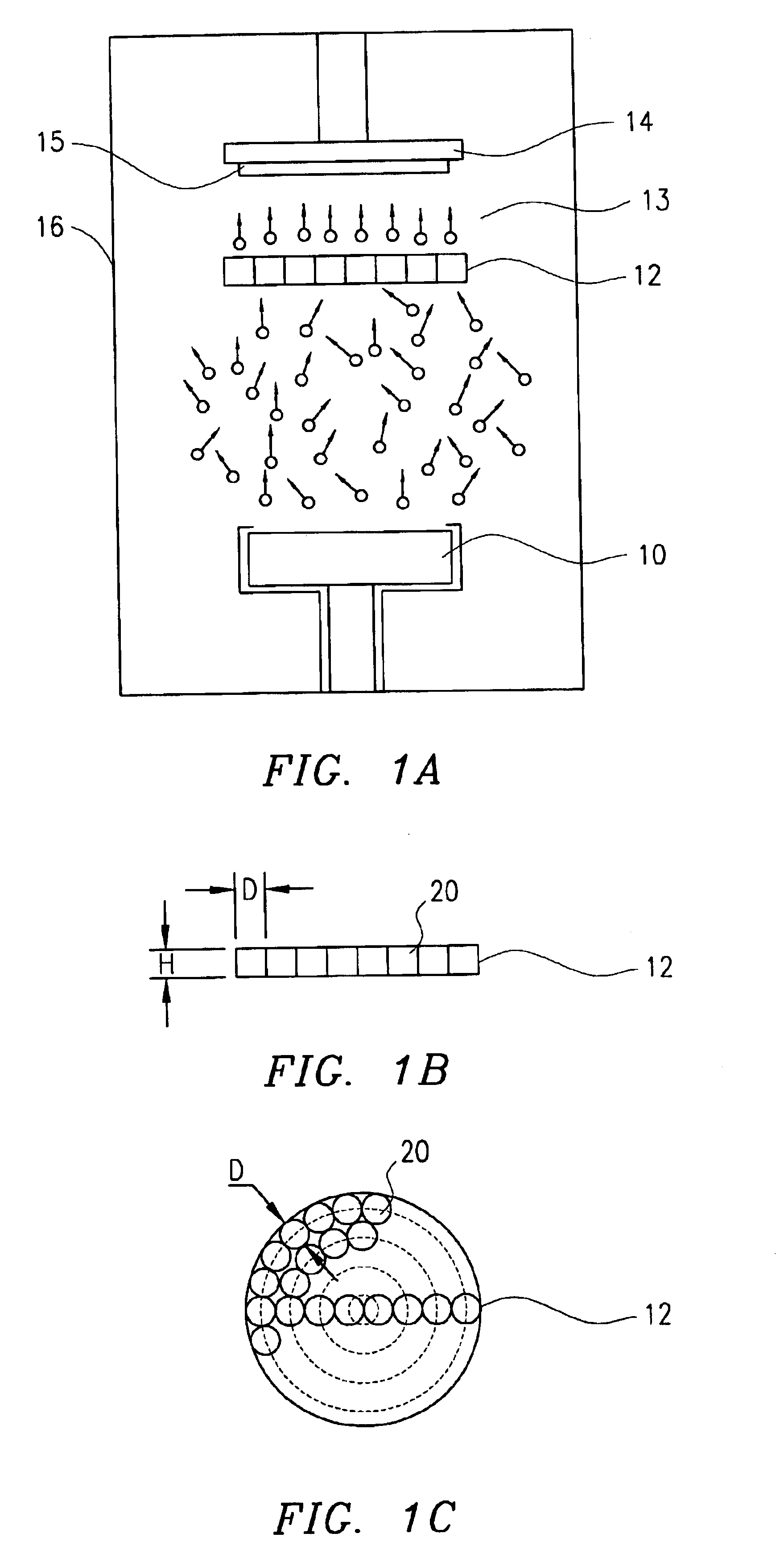
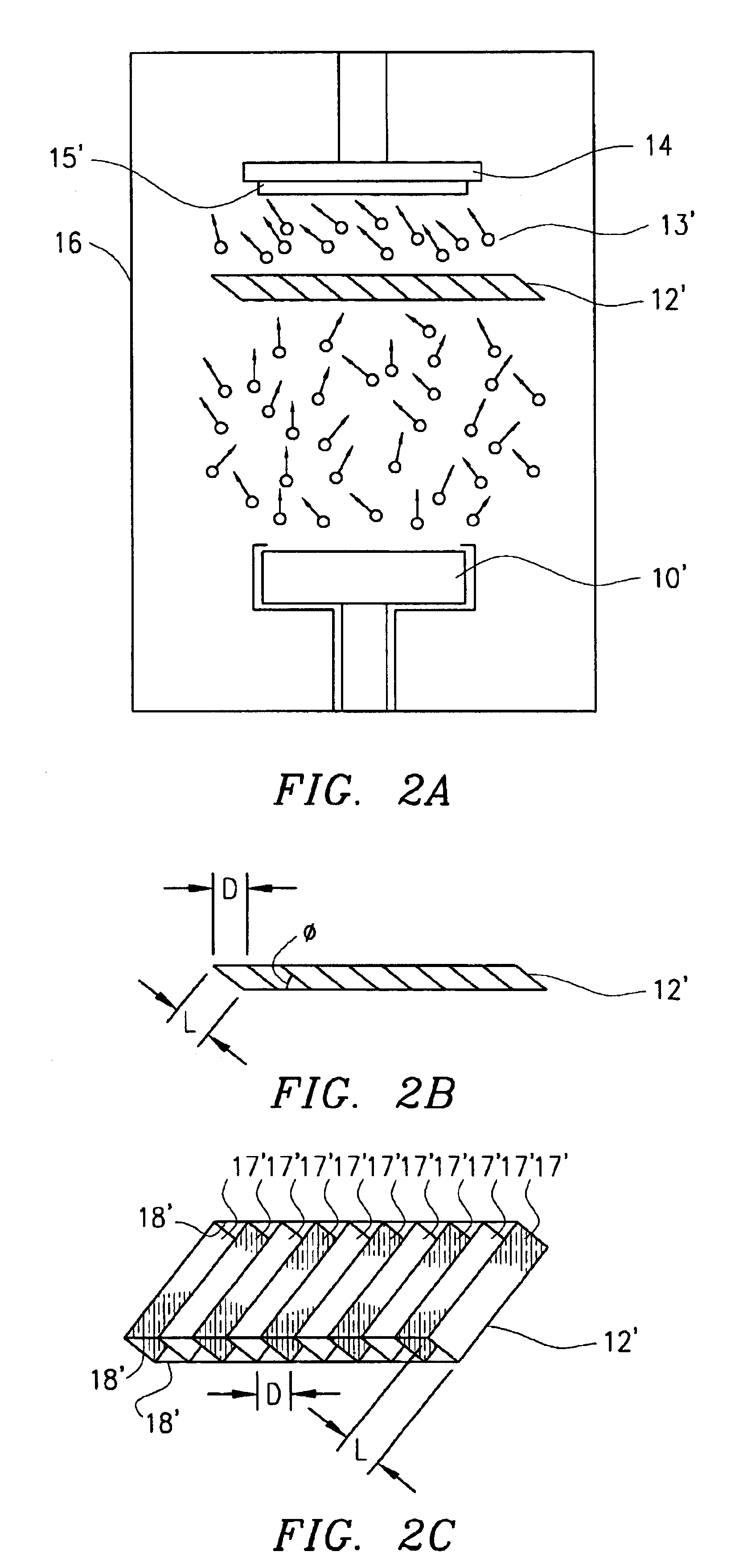
A cross-sectional view of the device in accordance with the present invention is illustrated in FIG. 2A. The difference between FIG. 1A and FIG. 2A is that in FIG. 2A an oblique collimator 12', rather than a perpendicular collimator, is shown. FIG. 2C is a 3-dimensional drawing of the collimator 12', which consists of supports 18' which span a plurality of rectangular sheets 17'. The collimator 12' can be constructed of metal or other conductor materials, insulate materials, or semiconductor materials. The number of the sheets 17' can be varied to achieve the desired passage size.
FIG. 2B is an end view of the collimator 12'. The collimator can be described by its aspect ratio D / L, and obliquing angle .theta., where D is the distance between two neighboring sheets 17', L is the width of a sheet 17' (i.e. the depth of the collimator), and .theta. the angle between the sheet 17' and the support 18'. As shown in FIG. 2A, the angled collimator 12' is placed between the substrate 15' and ...
second embodiment
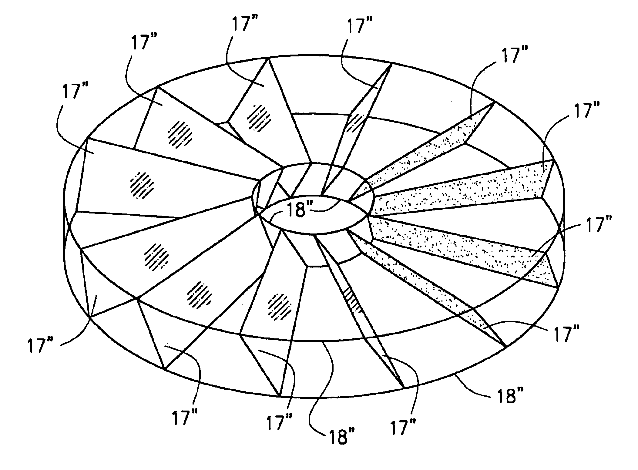
the oblique collimator is illustrated in FIG. 3A. The collimator is made of a circular-shaped support 18" and a plurality of trapezoid-shaped sheets 17". Sheets 17" can be made of conductor, insulator or semiconductor materials. This circular-shaped collimator is specially designed for a disk-shaped substrate. The sheets 17" are angled in the circumferential direction.
FIG. 3B is a sheet 17" having an increasing width toward its outer end which corresponds with the outer diameter of the collimator. This design ensures that the aspect ratio of the collimator is the same everywhere, and results in a desirable uniformity of thickness and uniform oblique effect. When this collimator is placed between a substrate and a target in a sputtering system similar to FIG. 2A, the resultant thin film on a disk substrate will have an angled column structure 21, as shown in FIG. 4. The columns angle in a circumferential direction with respect to the substrate surface of the disk substrate. This angl...
PUM
| Property | Measurement | Unit |
|---|---|---|
| angle | aaaaa | aaaaa |
| height | aaaaa | aaaaa |
| depth | aaaaa | aaaaa |
Abstract
Description
Claims
Application Information
 - R&D
- Intellectual Property
- Life Sciences
- Materials
- Tech Scout
- Unparalleled Data Quality
- Higher Quality Content
- 60% Fewer Hallucinations
Browse by: Latest US Patents, China's latest patents, Technical Efficacy Thesaurus, Application Domain, Technology Topic, Popular Technical Reports.
© 2025 PatSnap. All rights reserved.Legal|Privacy policy|Modern Slavery Act Transparency Statement|Sitemap|About US| Contact US: help@patsnap.com


