System for projecting light on a work surface to produce an image for tracing

a technology of projecting light and work surface, which is applied in the direction of electrical programme control, program control, instruments, etc., to achieve the effects of compact and portable, accurate and time-saving, and allowing mobility and flexibility

Inactive Publication Date: 2004-05-04
STUART CHRISTOPHER J +1
View PDF13 Cites 36 Cited by
  • Summary
  • Abstract
  • Description
  • Claims
  • Application Information

AI Technical Summary

Benefits of technology

By way of summary, the present invention is directed to a system which brings accuracy and time savings to outlining a pattern for use in applications such as the construction and installation modular structures having edge trim detail. Preferably, this is accomplished by projecting an image of light onto a work surface. This light or laser projection system is compact and portable to allow mobility and flexibility when working within an occupied or active work environment.
An effect of the present invention is to provide greater placement accuracy during the installation of certain modular structures. Another object of the invention is to provide an apparatus that allows for dial-in placement accuracy of structures in near real-time, unlike the projection through a lens which cannot easily correct for unforeseen work site problems. Yet another object of the invention is to provide a system that is ruggedized and reliable, thereby decreasing down time and operating costs. Another object of the invention is to provide a system that has one or more of the characteristics discussed above but which is relatively simple to manufacture and assemble using a minimum of equipment. Still another object of the invention to provide an apparatus which is very mobile and easily transported from construction site to construction site.
Another object of the invention is to provide a system that incorporates many physical labor saving steps. Yet another object of the invention is to provide a system that is predictable and reproducible, thereby decreasing the possibility of variance and reducing overall operating costs. Another object of the invention is to provide a system that has one or more of the characteristics discussed above, but which is relatively simple to setup and operate.

Problems solved by technology

This dissection is necessary because of the limited available distance between the laser projector and the work surface at the installation site.

Method used


Image

  • System for projecting light on a work surface to produce an image for tracing
  • System for projecting light on a work surface to produce an image for tracing
  • System for projecting light on a work surface to produce an image for tracing

Examples


Embodiment Construction

The present invention and the various features and advantageous details thereof are explained more fully with reference to the non-limiting embodiments described in detail in the following description.

1. System Overview

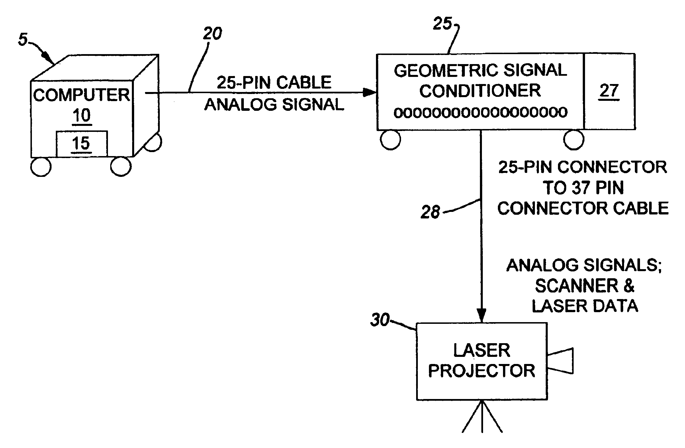
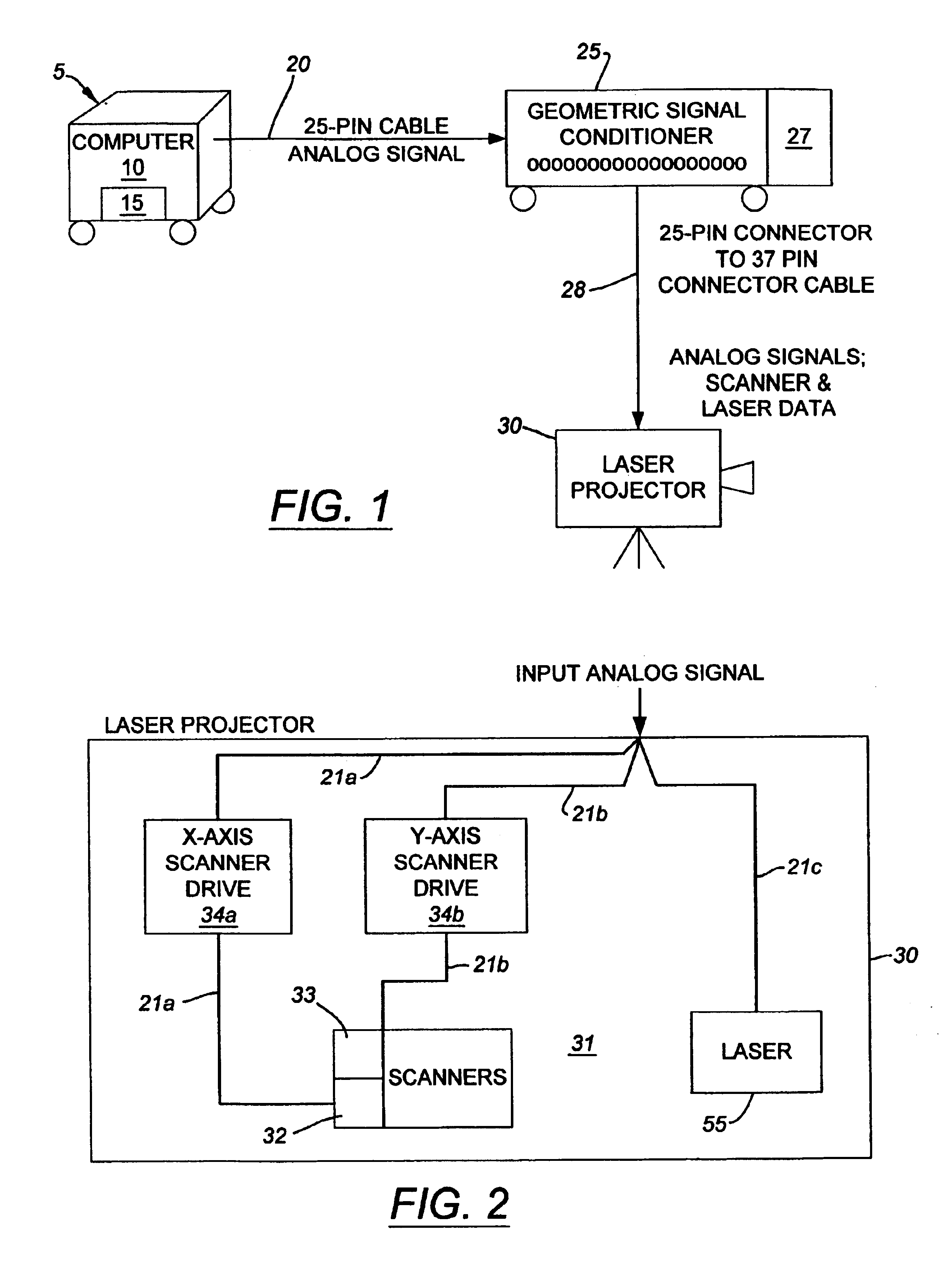
The present invention comprises a system of projecting light on a planar surface to produce an image for tracing comprising the steps of: creating a pattern; providing a projector having a light source; a signal conditioner operably connected to the projector (computer or otherwise); a computer operably connected to the signal conditioner; a scanner operably connected to the projector; a test pattern emanating from the projector for visually aligning an image to a sector; a grid operable aligned with the planar surface; and a geometric pattern projected on the planar surface; tracing lines along the pattern on the planar surface; cutting the pattern along the traced lines; discarding pieces of the planar surface outside the pattern; and placing edging or some other ma...


PUM


Abstract

A method and system of projecting light on a planar surface to produce an image for tracing is disclosed. The system includes a projector that has a light source and a signal conditioner that is operably connected to the projector. A computer is operably connected to the signal conditioner. A scanner is connected to the projector. A test pattern from the computer is projected from the projector through the scanners to visually align an image to a sector on a work surface. A grid is operably aligned with the work surface. A geometric pattern from the computer is then projected by the projector on the planar work surface for tracing. The method comprises the steps of creating a pattern, tracing lines along the pattern on the planar work surface, cutting the pattern along the traced lines, discarding pieces of the planar surface outside the pattern, and placing edging along an outer edge of the pattern.

Description

1. Field of the InventionThe present invention relates in general to the fields of building construction and interior decorating. More particularly, the present invention relates to a system and method for projecting light on a work surface to produce an image for tracing. Specifically, a preferred embodiment of the present invention relates to expediting the construction and installation of modular structures.2. Discussion of the Related ArtTraditional means of constructing geometric designs and constructing and installing modular structures with edge detail required a multiple person crew. Extensive man hours were wasted tediously pre-assembling the entire structure on the floor, mounting and dismounting the structure and the edge detail to make it fit the work surface, aligning the structure in the air, and then raising it and holding it in place for final installation. During some installations, crew members could also take portions of the edge detail and mark points on the modu...

Claims


Application Information

Patent Timeline
Patent Type & Authority Patents(United States)
IPC IPC(8): G05B19/18G01B11/24
CPCG01B11/24
Inventor MICHALSKI, MICHAELSTUART, CHRISTOPHER J.HOLPFER, DENNIS D.
Owner STUART CHRISTOPHER J
Why Eureka
Try Eureka