
Method and apparatus for monitoring the availability of nodes in a communications network

a communication network and node technology, applied in data switching networks, data switching details, multiplex communication, etc., can solve the problems of not all routers presently supporting multicast routing, inability to assume the availability of multicast routing, and excessive messages in nodes amounted to unnecessary cpu overheads

Inactive Publication Date: 2004-05-11
IBM CORP
View PDF11 Cites 85 Cited by
  • Summary
  • Abstract
  • Description
  • Claims
  • Application Information

AI Technical Summary

Problems solved by technology

The receipt of extraneous messages in a node amounts to an unnecessary CPU overhead.
However, with the efficiency of multicast, there are difficulties.
Unfortunately, not all routers presently support multicast routing.
Also, due to system administrators preferences, the availability of multicast routing can never be assumed.
(routers may not be configured to route multicast, even if they support such routing).
A common problem that affects tree routing algorithms is that any of the routing nodes may fail due to hardware or software problems.
In most cases the failure is not detected because there is no mechanism for monitoring the health of the routing nodes.
Another problem related to the routing of multicast messages is that traditionally most WAN do not support multicast communications.
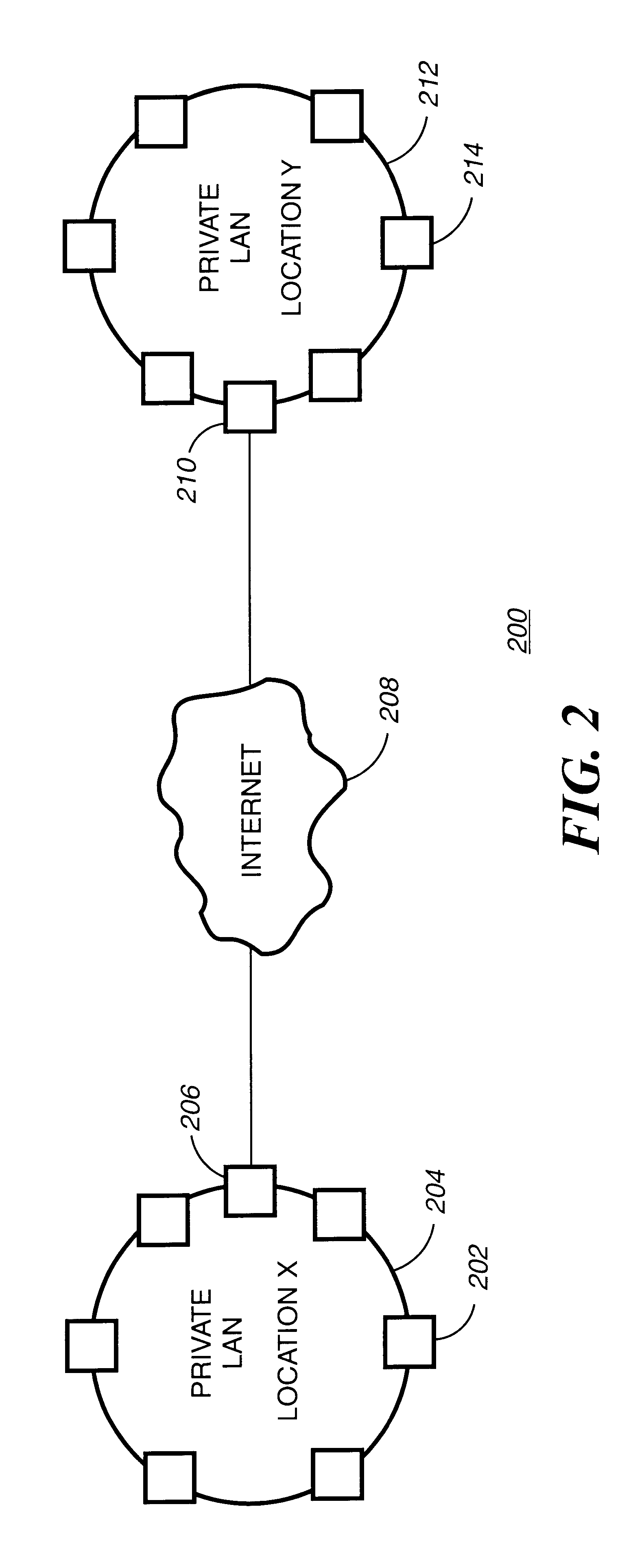
This can be especially problematic in a network topology where two or more LANs (Local Area Networks) are separated by a WAN.
Another problem related to the routing of multicast messages is that it becomes difficult to contain the spread of the routing of multicast messages.
More specifically, it becomes very difficult to contain multicast traffic to only selected subnetworks, if they are attached to the same routing node.
Still another problem related with multicast routing is that the shortest path optimization made by multicast tree algorithms may overload routing points which are connected to several nodes with an excess of datagram messages to forward.
Typical multicast routing protocols do not take into account the balancing of the routing burden which is imposed to the routing nodes.
Another aspect of the multicast technology is that not all hardware is capable of n routing multicast datagrams.
The problem that arises in the deployment of tunnels is that typically the configuration of the tunnel is fixed.
In this case, a disruption of multicast links will happen if the hardware in any of the tunneling endpoints fails.
A problem similar to the one faced by multicast tree algorithms arises when any of the tunneling endpoints fails, and the communication path or multicast datagrams is broken.
The problem of detecting hardware failures in a communications network, or in a distributed computing system is very difficult to solve.
Typical heartbeating solutions are not based on multicast protocols, since the failure of the routing points amounts to a disruption in multicast communications.
However, the use of non-multicast protocols, cannot take advantage of the flexibility of the multicast messages, which reduce network traffic and such non-multicast algorithms demand too much bandwidth from the communications network.
Still other problems that exist with management of current communications networks is the need to provide a simple program that can work across a variety of disperse, distinct and non-homogeneous network architectures with a small code foot print to work in small computers and routers, but that provides a correct hierarchal structure that is self contained and to enable the leveraging of multicast tunneling structure which is capable of dynamically routing the multicast messages to the entire communications network, independently of the network topology.

Method used


Image

  • Method and apparatus for monitoring the availability of nodes in a communications network
  • Method and apparatus for monitoring the availability of nodes in a communications network
  • Method and apparatus for monitoring the availability of nodes in a communications network

Examples


Embodiment Construction

However, it should be understood that these embodiments are only examples of the many advantageous uses of the innovative teachings herein. In general, statements made in the specification of the present application do not necessarily limit any of the various claimed inventions. Moreover, some statements may apply to some inventive features but not to others. In general, unless otherwise indicated, singular elements may be in the plural and visa versa with no loss of generality.

Glossary of Terms Used in This Disclosure

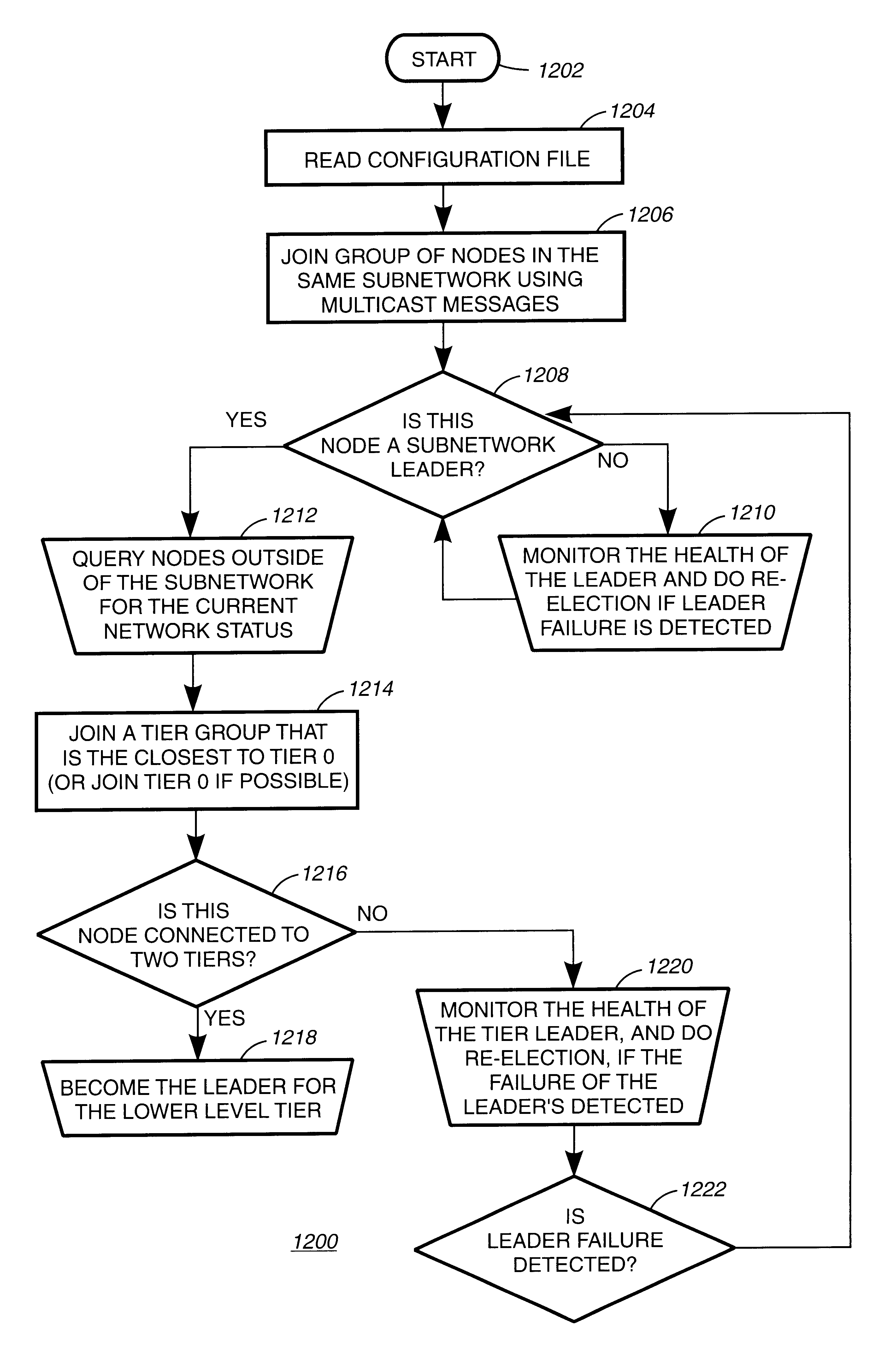
Beacon Node--a node in a communications network or parallel computer system that sends and receives messages via multicast over a subnetwork. The beacon node produces a periodic heartbeat message that is broadcast over a subnetwork.

Beacon Program--a program at a beacon node for sending beacon messages and receiving master lists of beacon heartbeat messages.

Channel--another name for a multicast group.

Configuration file--a file containing all the nodes in a subnetwork an...


PUM


Abstract

A method and apparatus for managing communications in a distributed computing system wherein a plurality of computers are interconnected with a communications network. At least a portion of the network is established as a subnetwork with at least one node attached to the subnetwork. The node in the subnetwork multicast a verification message over the subnetwork in which it is attached. A subnetwork leader for each subnetwork is identified and gathers the verification message sent from each node in the subnetwork. The subnetwork leader assembles each verification received into a subnetwork list. The subnetwork list is sent a node identified as the network leader. The network leader assembles each subnetwork list received into a master list and sends this master list out to the subnetwork leaders. In turn, the subnetwork leaders for each subnetwork multicast the master list out to each node.In one embodiment, the communications between each subnetwork leader and the network leader is over multicast.In another embodiment, a system and computer readable medium is disclosed to carry out the above method.

Description

PARTIAL WAIVER OF COPYRIGHTAll of the material in this patent application is subject to copyright protection under the copyright laws of the United States and of other countries. As of the first effective filing date of the present application, this material is protected as unpublished material. However, permission to copy this material is hereby granted to the extent that the copyright owner has no objection to the facsimile reproduction by anyone of the patent documentation or patent disclosure, as it appears in the United States Patent and Trademark Office patent file or records, but otherwise reserves all copyright rights whatsoever.Not Applicable1. Field of the InventionThis invention relates to fault tolerant digital communications systems, in general, and more specifically to fault tolerant packet transmission systems involved in the management of multicast communications. Also, this invention generally relates to the field of distributed computing, wherein a plurality of com...

Claims


Application Information

Patent Timeline
IPC IPC(8): H04L12/56H04L12/18
CPCH04L12/1854H04L12/1868H04L45/02H04L45/16H04L45/26H04L45/46
Inventor NOVAES, MARCOS N.
Owner IBM CORP
Learn More