Display uniformity calibration system and method for a staring forward looking infrared sensor

a technology of infrared sensor and uniform calibration system, which is applied in the field of infrared detection systems, can solve the problems of adjusting the sensor dynamic range, the optical performance of a typical flir system, and the optical component itself being a source of nois

Inactive Publication Date: 2004-05-18
RAYTHEON CO
View PDF13 Cites 4 Cited by
  • Summary
  • Abstract
  • Description
  • Claims
  • Application Information

AI Technical Summary

Benefits of technology

In a refinement of this method, the adjacent high and low BF levels of the present and adjacent dynamic ranges overlap (i.e., for the same scene, the BF obtained in either dynamic range is within the range of acceptable BF levels for these dynamic ranges), thereby providing a hysteresis effect against switching frequently between adjacent dynamic ranges. The combination of LE initialization calibrations and automatic dynamic range adjustment eliminates the need for in-flight touch-up calibration. Uniformity in-flight is maintained as long as the BF encountered during operation and the BF obtained during calibration of the LE set for the dynamic range used is between the low and high BF levels obtained in the calibration of the corresponding RE set. Thus, the only limitation of this method is the inability of the low and high BF levels of the RE calibration to span the corresponding dynamic range.
The next step of this method is to calibrate a level equalization for each anticipated dynamic range at each power-up initialization (i.e., calibrate dynamic ranges which may be used during the mission). During the LE calibration, the entrance pupil of the FLIR is aligned to a thermal reference source which is adjusted to the proper temperature in combination with adjusting the dynamic range to obtain a bucket fill that falls between the corresponding pair of responsivity equalization bucket fill levels. The LE calibration is then performed. LE initialization calibrations starts with the lowest dynamic range (with the TRS as cold as possible) and continues to successively higher dynamic ranges (with TRS adjusted hotter) until all anticipated dynamic ranges are covered (order chosen again assumes optics heat up with time). An attempt is made to center the BF in the second dynamic range setting, but if the TRS requires excessive slewing then the calibration may be skewed to a lower BF. After the second dynamic range, the rest of the anticipated dynamic ranges are calibrated with a BF towards the lower end of the dynamic range, but still above the low BF of the corresponding RE set. Note that calibrating toward lower BF saves time and places the calibration in a regime that one would encounter more often (i.e., when switching to a higher dynamic range the BF will first be at the low end of the dynamic range).
The third step involves choosing the initial dynamic range (with its associated LE set, RE set and gain) based on the unpowered TRS and present scene / optics temperature. In the final step, during an operational time period immediately following initialization, as needed the algorithm changes to another of the plurality of dynamic ranges if the scene / optics temperature results in a bucket fill that exceeds threshold levels (too low or high) of the initial dynamic range. The BF of the sensor is constantly monitored with filtering so that very temporary changes in the scene caused by movement of the gimbaled telescope will not result in unnecessary switching of dynamic ranges. As a refinement of this method, adjacent high and low BF levels of two adjacent dynamic ranges overlap, thereby providing a hysteresis effect against switching frequently between adjacent dynamic ranges.
Redoing of the whole process above may be required. In the case that the two point RE calibration can not span across most of the dynamic range due to hardware and physics constraints when the FLIR is hot, an alternate RE scheme is used spreading the two BF points as far apart as is reasonably possible. The alternate RE scheme uses a simple algorithm which reduces the span of each two point RE calibration and allows for lower gain adjustment in order to achieve this reduced span. Original RE calibrations will check the need for and flag the use of the alternate RE scheme based on the BF obtained when the TRS is at its coldest. The degraded calibration may not adequately cover the range of BF levels encountered in operation and in extreme cases the BF during LE initialization may not fall between the BF levels of the two point RE calibration. A warning system was thus developed so that in cases of a degraded RE calibration, a recommendation to redo the RE calibrations is made when the FLIR is cooler. In the warning system, a RE quality factor is calculated. Since the spread in BF in the RE calibration is dependent upon the BF obtained when the TRS is cold, the RE quality uses this BF value which is obtainable at initialization before the start of RE or LE calibration.

Problems solved by technology

Therefore, the optical components themselves are a source of noise to the FLIR systems.
Another limitation on the optical performance of a typical FLIR system is due to the fact that the optical components do not have perfect transmissivity.
Since staring sensors are DC coupled devices which monitor infrared energy levels (photon flux) varying exponentially with temperature, it should be appreciated that given a range of sensor output levels as they are correlated to scene energy levels, there are problems and opportunities to adjust the sensor dynamic range to accommodate the scene's dynamic range.
Sensor inputs that are too low result in noisy output while inputs that exceed the sensor's dynamic range result in saturated video.
Inasmuch as the amount of power available for the TRS is limited, the capabilities of the TRS are limited as well and given that the hardware performing the calibration may take a while, it necessarily requires a significant amount of time for the calibration operation to occur.
This is undesirable, especially during operation since the vital function of the FLIR system is interrupted.
Thus, the only limitation of this method is the inability of the low and high BF levels of the RE calibration to span the corresponding dynamic range.
Also, the calculated values of the gain of each gain state and the BF corresponding to no photon flux are checked against the expected nominal design values and deviations larger than expected are flagged as possible hardware problems.
The degraded calibration may not adequately cover the range of BF levels encountered in operation and in extreme cases the BF during LE initialization may not fall between the BF levels of the two point RE calibration.

Method used


Image

  • Display uniformity calibration system and method for a staring forward looking infrared sensor
  • Display uniformity calibration system and method for a staring forward looking infrared sensor
  • Display uniformity calibration system and method for a staring forward looking infrared sensor

Examples


Embodiment Construction

Illustrative embodiments and exemplary applications will now be described with reference to the accompanying drawings to disclose the advantageous teachings of the present invention.

While the present invention is described herein with reference to illustrative embodiments for particular applications, it should be understood that the invention is not limited thereto. Those having ordinary skill in the art and access to the teachings provided herein will recognize additional modifications, applications, and embodiments within the scope thereof and additional fields in which the present invention would be of significant utility.

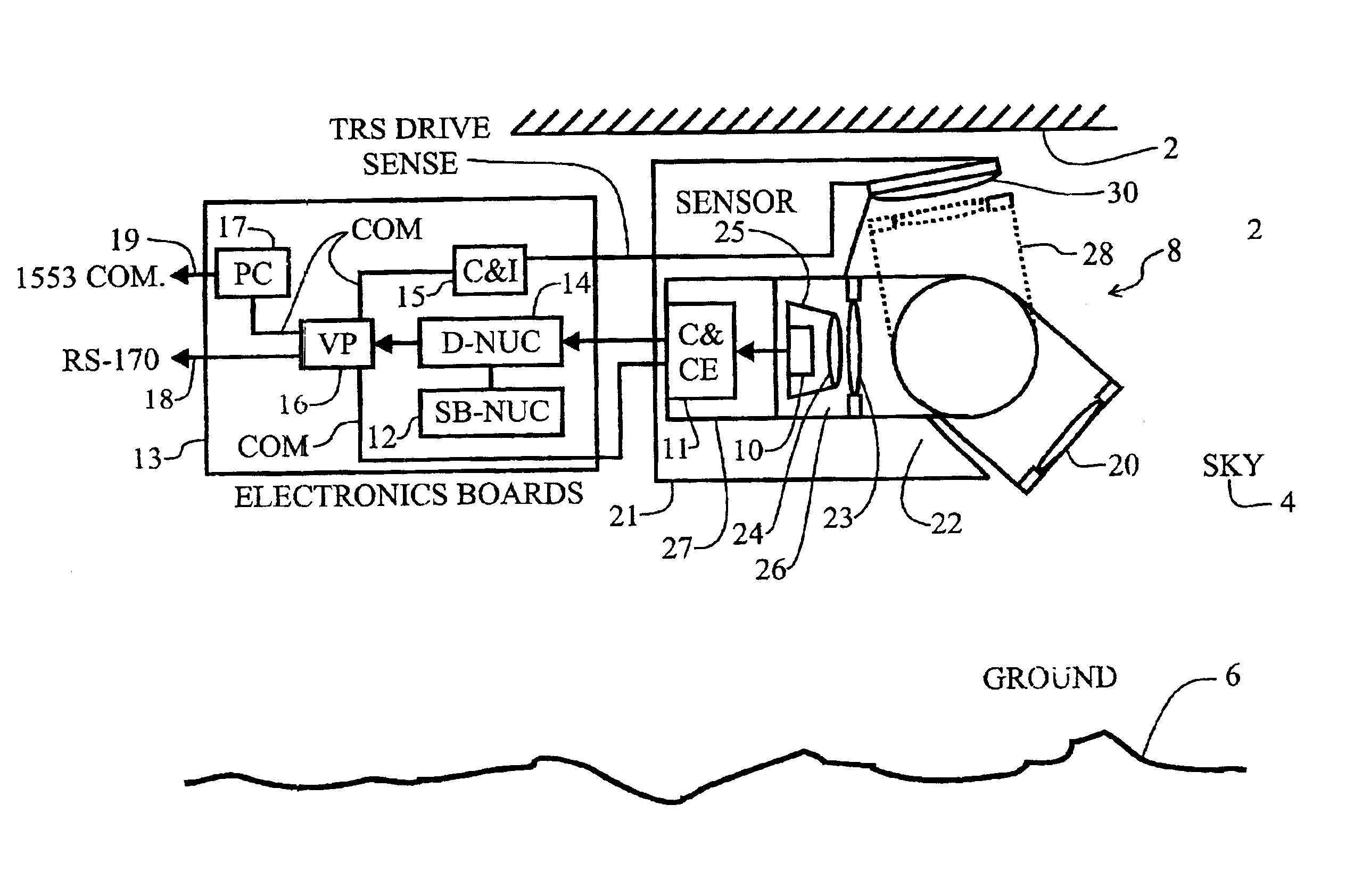
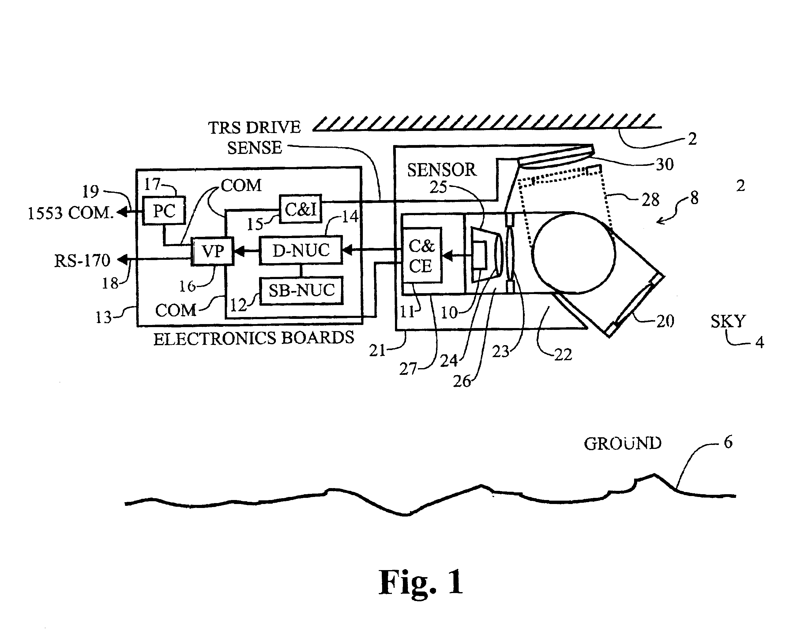
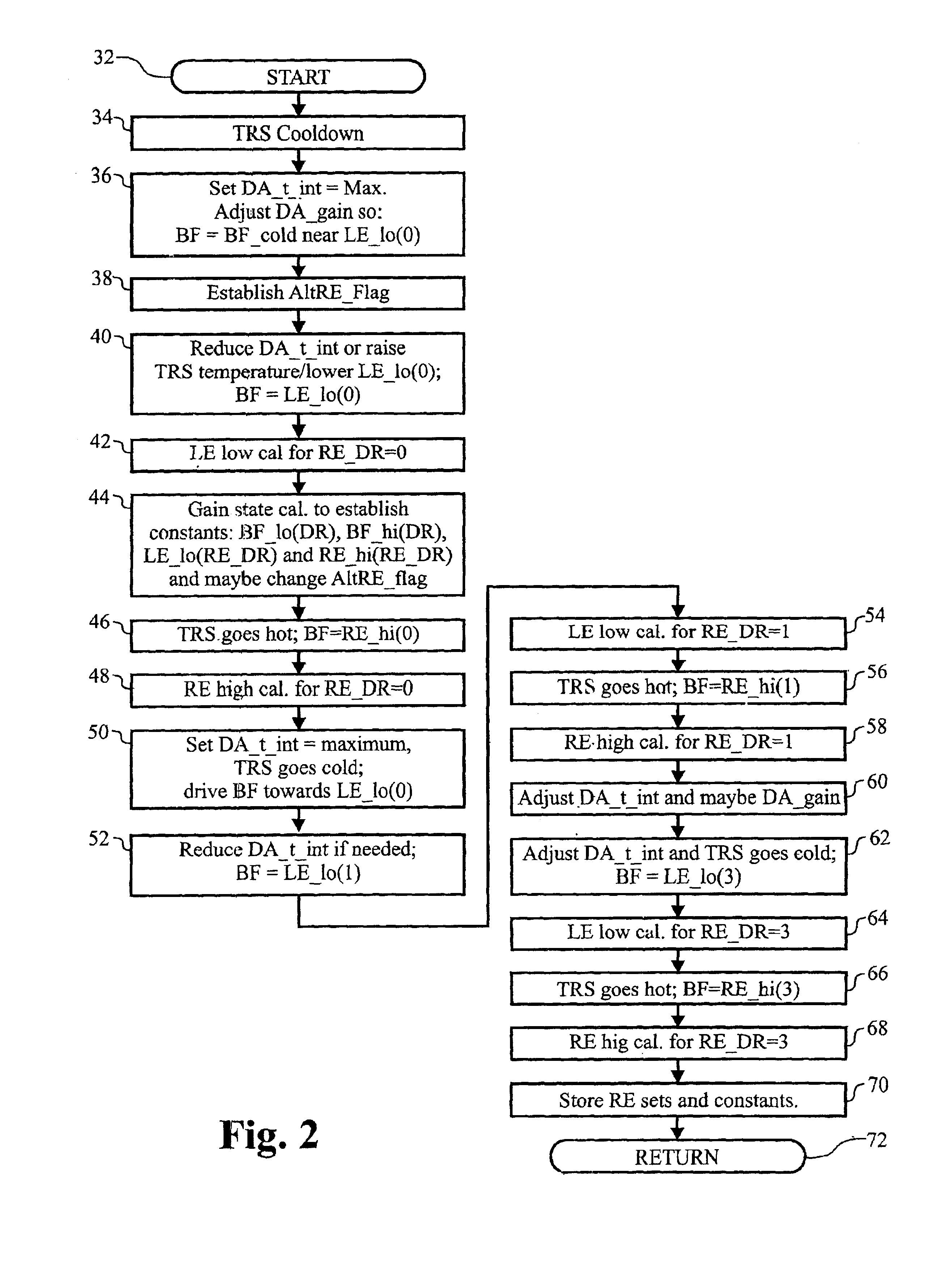
FIG. 1 is a functional block diagram of an illustrative embodiment FLIR system as it might be deployed on an aircraft. The present invention utilizes an algorithm that is employed in the initialization procedures of forward-looking infrared ("FLIR"). The aircraft 2 operates in the sky 4 above the ground 6. A FLIR pod 8 is mounted to the aircraft 2. Within the FL...


PUM


Abstract

A method and system for maintaining uniformity in a FLIR display. During a one-time initialization procedure, a plurality of dynamic ranges are defined by covering a specific range of bucket fill levels when in a certain gain. To cover all dynamic ranges possible, a plurality of pairs of responsivity equalization (RE) calibrations (each pair producing a RE set of pixel gain corrections) are also accomplished in the same one time initialization period. A plurality of corresponding level equalization (LE) calibrations (each using the appropriate calibrated RE set and producing a LE set of pixel level corrections) for each anticipated dynamic range are made at every power-up initialization. Each of the calibrations is done with respect to a thermal reference source to produce a uniform scene at the desired bucket fill level. An algorithm is employed which forces the two bucket fill points defined during the responsivity calibration to span as far as possible the dynamic range and forces the level equalization bucket fill point to fall within the two bucket fill points of the responsivity calibration. Then, during an operational time period, the scene and optics temperatures are monitored, and if the average bucket fill value exceeds the bucket fill range of the present dynamic range, the presently selected dynamic range is changed to a second dynamic range (gain is changed along with the RE set and LE set). The dynamic ranges are designed to overlap so that a hysteresis effect is achieved. The pre-calibrations and automatic dynamic range switching prevent saturation and create the best uniformity (lowest fix pattern noise) possible while allowing for continuous operation of the FLIR system, thus eliminating the interruption caused by the prior art touch-up calibration procedure.

Description

1. Field of the InventionThe present invention relates to infrared detection systems. More specifically, the present invention relates to systems and methods for providing dynamic range control and non-uniformity calibration of staring infrared imaging systems.2. Description of the Related ArtInfrared imaging systems have achieved a wide level of deployment in industrial, commercial and military applications. The leading edge of technological development has typically been in the military arena as the ability to generate infrared images has many advantages in both tactical and strategic applications. This is particularly true in airborne systems.Forward looking infrared (hereinafter "FLIR") systems have been used in airborne applications for many years. Such systems typically employ a focal plane array ("FPA") of infrared image sensing pixels that are coupled with an optical system which views a scene through an entrance pupil of the FLIR system. The FPA is typically housed within a...

Claims


Application Information

Patent Timeline
Patent Type & Authority Patents(United States)
IPC IPC(8): H04N5/33H04N5/217H04N5/353H04N5/355H04N5/363H04N5/365
CPCH04N5/235H04N5/2352H04N5/33H04N5/365H04N23/72H04N23/70H04N25/67
Inventor HUNIU, LEE J.
Owner RAYTHEON CO
Why Eureka
Try Eureka