Membrane desiccation heat pump

a membrane desiccation and heat pump technology, applied in the direction of heating types, domestic cooling devices, separation processes, etc., can solve the problems of large power input for the compression cycle, freon.tm. is not as efficient as freon.tm, and the gaseous environment is considered unsa

Inactive Publication Date: 2004-05-25
KORIN AMOS
View PDF105 Cites 109 Cited by
  • Summary
  • Abstract
  • Description
  • Claims
  • Application Information

AI Technical Summary

Benefits of technology

Another object of the present invention is to provide a membrane desiccation air conditioning system, which permits a greater degree of independent control of temperature and humidity for achieving parameter levels in desired regions of the comfort zone than prior art systems.
A further object of the present invention is to provide an open system membrane desiccation air conditioner having a broad range of applications and being capable of net introduction of either heat or mechanical energy from an external source and net removal of heat energy relative to the air conditioning system for greater flexibility and control of comfort zone parameters.
The present invention involves a membrane desiccation heat pump for use in association with a gaseous flow system adapted to move a gaseous process fluid, such as air, containing a quantity of moisture vapor content. In a preferred embodiment, the cooling system includes (a) humidification means, e.g., a gas-liquid contactor, operable to add vapor of a vaporizable liquid fluid to a process gaseous fluid, (b) a moisture vapor membrane permeator, (c) means for passing the process fluid through the membrane permeator to dry the process fluid and substantially reduce the quantity of moisture vapor in the process fluid, thereby separating the vapor from the gaseous process fluid and (d) vapor removal means for removing the concentrated vapor from the from the membrane permeator. An evaporation process utilizes heat from one of the fluids or from both for the latent heat of vaporization of the liquid, to reduce the temperature thereof and simultaneously establish a desirable humidity level in such gaseous process fluid.
One feature and advantage of the present invention is that the membrane desiccation heat pump permits a substantial import of energy from an external source, such as an alternative or low level energy source, into the system, and a substantial removal of heat energy from the system. Thus, the present invention provides a very efficient heat pump both for the purpose of either cooling or heating.
The liquid-gas contactor facilitates mass transfer of liquid vapor from a liquid into a gas while simultaneously removing latent heat from the liquid and thereby reducing the temperature of both. It also acts as a direct-contact heat exchanger that enables a heat transfer from a fluid that has to be cooled to a circulating fluid. It may be any unit that operates on a principle common in the industry such as spray or atomizing, dripping, sprinkler, wet pad, packed column, plates column, baffle tower or any type of cooling tower. It could also be a membrane contactor having any of the configurations described above for the membrane permeator assembly, however, in this case, it would enable the evaporation from the liquid to the gas phase. Other possible embodiments for such a contactor include a humidifier or any type of evaporator, for example, a short tube evaporator or a long tube evaporator, or a flash evaporator.

Problems solved by technology

In most cases, chloro-fluoro carbon gases, e.g., Freon.TM., were used, but recently such gases have been considered environmentally unsafe.
Conventional alternatives to Freon.TM. are not as efficient as Freon.TM., and thus systems using the compression-expansion cycle require a relatively large input of power for the compression cycle.
Some of the problems associated with desiccant air conditioners are the need for removal of latent heat of condensation and adsorption from the desiccant bed and desiccant material during the adsorption cycle, the need for thermal energy for the desiccant regeneration cycle and the need to cool the desiccant after the regeneration.
Furthermore, desiccant wheel machines are cumbersome to build and require a high level of maintenance.
Although membranes have been used in various separation applications, their use for heat pump systems has been limited.

Method used


Image

  • Membrane desiccation heat pump
  • Membrane desiccation heat pump
  • Membrane desiccation heat pump

Examples


Embodiment Construction

Before proceeding with a description of the present invention, it is well to define certain terms as used herein.

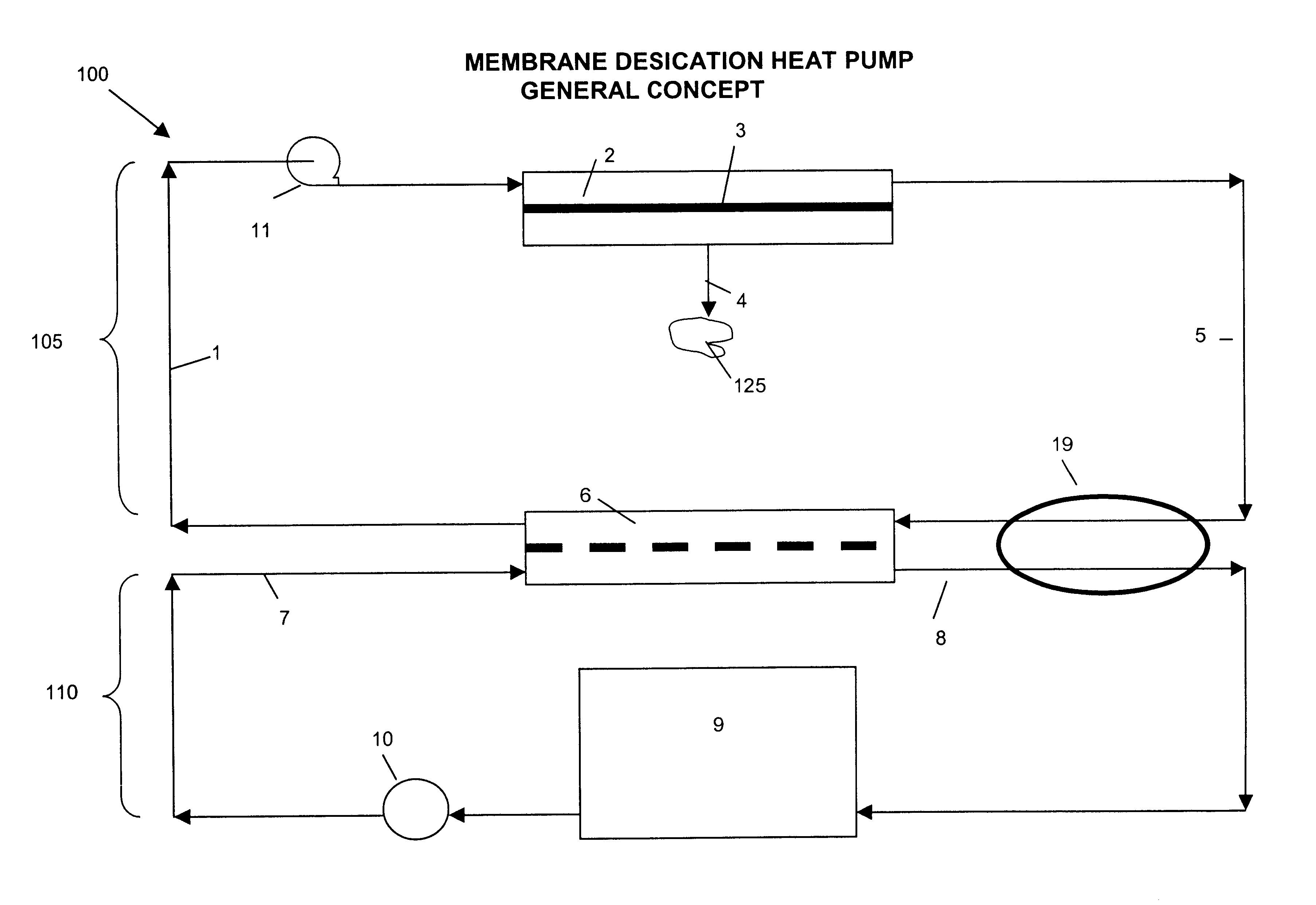
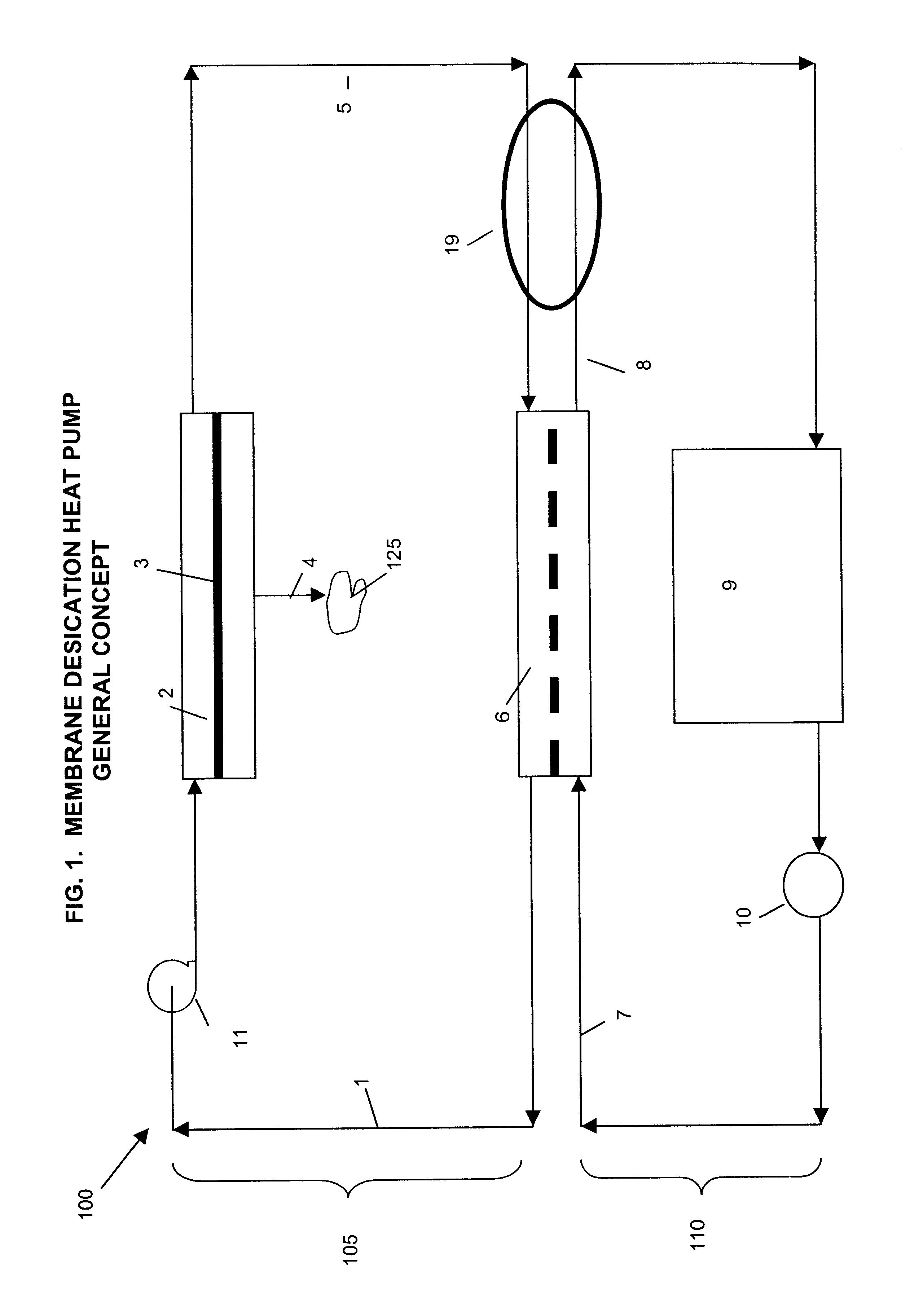
A heat pump is a system that utilizes a thermodynamic process that takes thermal energy from a low temperature heat source and releases it at higher temperature utilizing an input of energy from another source.

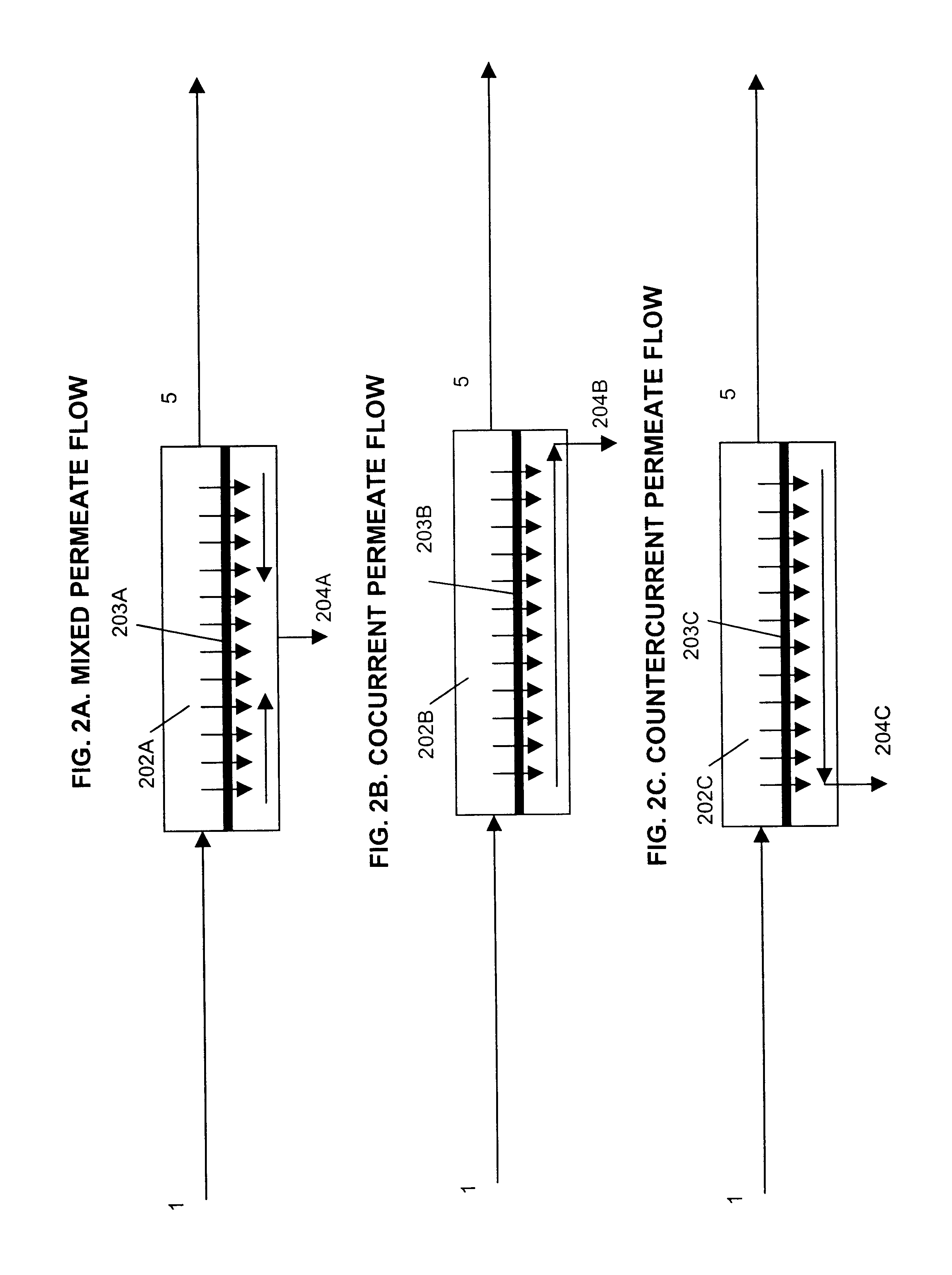
A membrane is a semi permeable barrier capable of selectively permeating certain constituents of a fluid mixture.

A membrane permeator is a self-contained assembly of membrane packaging, including all required housings and piping components, capable of rendering perm selective separation of a fluid mixture.

Desiccation is a process for removing vapor of one or more liquids out of a gas containing the vapor, resulting in vapor-depleted or dry gas. Usually this is done by an adsorption material such as a zeolite or a silica gel. However, it can be done by absorption for example, absorption of water vapor by sulfuric acid.

A fluid is a substance with no reference configur...


PUM


Abstract

There is provided a system for pumping thermal energy. The system includes (a) a membrane permeator for removing vapor from a process gas and for providing a vapor-depleted process gas, and (b) a gas-liquid contactor for adding vapor from a liquid to a vapor-depleted gas to produce a vapor-added process gas. The system transfers a quantity of thermal energy from the liquid to the vapor-added process gas, and is also capable of upgrading the thermal energy to a higher temperature. The system may be used for various heat pump applications including chilling and waste heat or low level heat recovery.

Description

1. Field of the InventionThe present invention relates generally to a transfer of thermal energy, and more particularly, to heat transfer arrangements employing a membrane desiccation heat pump for both heating and cooling applications.2. Description of the Prior ArtA cooling of a gaseous fluid containing humidity and, in particular, a cooling of humid air, is desired in many circumstances. Cooling of ambient atmosphere is often desired in buildings, domestic dwellings, in appliances such as refrigerators, and in storage rooms and the like. It is also desired in delivery vehicles and trucks, and in aircraft and marine craft. Other applications are natural gas cooling for removal of natural gas liquids or providing of controlled inert atmosphere to industrial processes such as paint drying, food drying and clean rooms.Cooling systems using water vapor as working fluid are among the oldest in the art of producing cold. Early processes made use of principles of both compression and ads...

Claims


Application Information

Patent Timeline
Patent Type & Authority Patents(United States)
IPC IPC(8): B01D53/22F24F3/14F24F5/00F24F3/12F25B30/00F25B29/00
CPCB01D53/22F24F3/1417F24F5/0007F24F5/0035F25B30/00F24F2003/1435F24F2003/144F25B29/00Y02B30/545B01D53/268Y02B30/54
Inventor KORIN, AMOS
Owner KORIN AMOS
Why Eureka
Try Eureka