Ion generator apparatus

a technology of ion generator and generator device, which is applied in the direction of tubes with electrostatic control, nuclear reactors, greenhouse gas reduction, etc., can solve the problems of rapid ion loss of anodes, and achieve the effects of high current density, high surface area ratio, and greater flexibility and control of plasma regimes

Active Publication Date: 2019-08-27
AUREON ENERGY LTD
View PDF14 Cites 1 Cited by
  • Summary
  • Abstract
  • Description
  • Claims
  • Application Information

AI Technical Summary

Benefits of technology

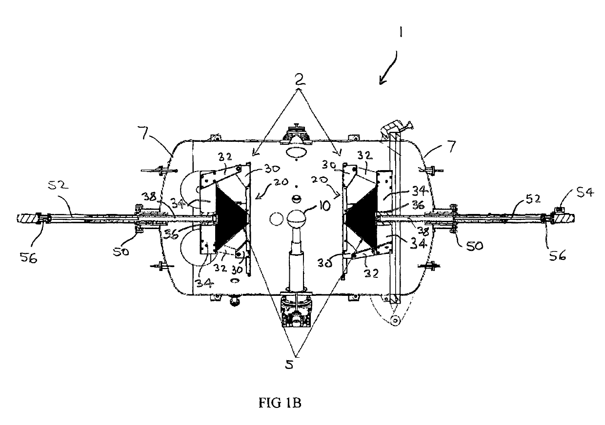
[0005]In another aspect, the present disclosure addresses issues with prompt ignition of plasma which are overcome by the design of adjustable cathodes that can be moved closer to or farther from the anode. This enables ease of plasma ignition and subsequent movement away from the anode to further adjust the electron and ion concentration and voltage potential. The utilization of movable cathodes enables greater flexibility and control of plasma regimes.
[0007]In another aspect, the present disclosure relates to a spherical anode with distance adjustable dual cathodes for generating positive ions through a non-equilibrium collisional plasma powered by a direct current power supply. The ions generated can form dense, stable, multiple plasma double layers. Without being bound by theory, these double layers are regions of separated charge that serve to further augment the ion density, radio frequency emission, and other phenomenon across the electromagnetic spectrum. The present apparatus, because of the ability to move the cathodes with precision, can be operated under a wide range of plasma conditions, including glow discharge, anode tufting, high power quiescent, multiple double layers, and a high power discharging mode which produces copious amounts of energy within the discharges. In addition, electromagnetic field generators are used to further control the many plasma regimes.
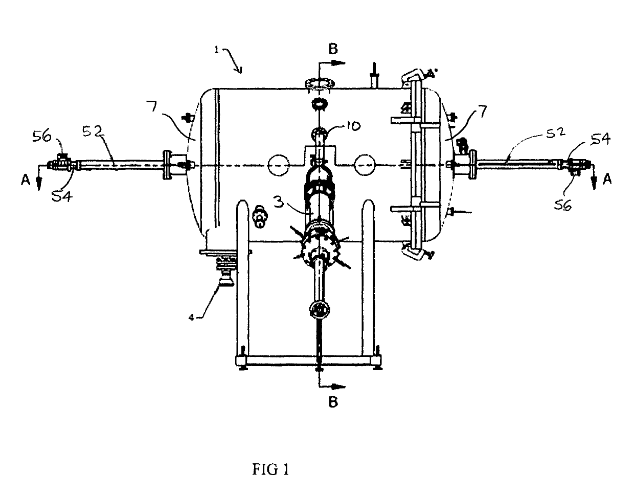
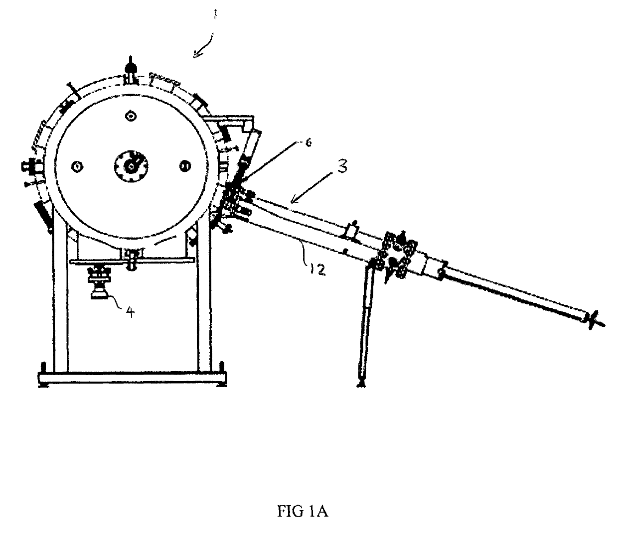
[0008]In another aspect, the present disclosure relates to an apparatus that can ignite a spherical high voltage, high current discharge in a variety of gas atmospheres and pressures, enabled by adjustable distance cathodes in relation to the anode, and can further direct the plasma by use of electromagnetic field generators. The anode can have various configurations including a solid metal, semi-metal, or coated anode; or can be a hollow anode that diffuses high pressure gas at a controlled rate into the surrounding atmosphere in a chamber. The hollow anode configuration leads to electron collisions occurring at greater distances from the anode surface than when the anode is solid, since the diffusion of the gas from the surface pushes the gas breakdown in the plasma to greater distances from the solid surface. Because of the spherical geometry, extremely high electric fields are obtained and stable double layers form reproducibly and reliably. The electromagnetic field generators are of a design by which a vector electromagnetic field can be generated as either positive or negative and by which the direction of the field can easily be changed to oppose or attract ions and electrons thus providing further control over the various plasma regimes. The conical geometrical shape of the electromagnetic generators is of a design by which a focused electromagnetic field is developed having the effect of a unipolar magnetic field. In certain aspects, the geometry of the electromagnetic field generator can be spherical, in other aspects, conical, or employ other geometries.

Problems solved by technology

Without being bound by theory, a high surface area ratio between the cathode and anode enables high current density to impinge upon the anode which results in rapid thermal heating of both the plasma and anode, which results in rapid ion loss from the anode.

Method used


Image

  • Ion generator apparatus
  • Ion generator apparatus
  • Ion generator apparatus

Examples


example 1

[0027]FIG. 3 is an image of a typical discharge on a spherical anode in hydrogen gas in a chamber according to an embodiment of the present invention.

example 2

[0028]FIG. 4 is a graph depicting the Paschen curve for cathodes at various distances (●—3.81 cm, X—7.62 cm and □—15 cm) from an anode in a chamber according to an embodiment of the present invention. All of the distances were adjusted while the experiment was underway, which shows the utility and advantage of using the adjustable cathodes, as the cathodes are moved away from the anode during the discharge. In a planar electrode configuration, the distance-gas pressure factor (x-axis) generates a single u-shaped curve. However, with the present configuration of two cathodes and spherical anode, a departure from the single curve is encountered as a function of cathode distance.

example 3

[0029]FIG. 5 shows the stable various regimes of plasma produced by a discharge in hydrogen gas at ˜5 torr while increasing the current (from top to bottom, from ˜0.2 amps to 8 amps). Of note are the numerous double layers which are reproducible.


PUM


Abstract

An ion generator including a vacuum chamber; an anode in the chamber, and two movable cathodes in the chamber whereby the distance of the cathodes relative to the anode can be varied. A servo actuated motor can be operably connected to each movable cathode to move the cathodes in the chamber and modify the plasma generated.

Description

CROSS-REFERENCE TO RELATED APPLICATION[0001]This application claims the benefit of U.S. Provisional Patent Application Ser. No. 62 / 547,455 filed Aug. 18, 2017.FIELD OF DISCLOSURE[0002]This disclosure relates to the field of plasma generating devices for high temperature plasma and fusion research.BACKGROUND OF THE DISCLOSURE[0003]Some ion generators for generating plasma use fixed anode and cathode distances, thereby preventing the ability to tune the plasma to specific electric potentials and desired settings. Other ion generators utilize the body of the apparatus as the cathode. For plasma generation, precise positioning of the cathode(s) relative to the anode is desired.SUMMARY OF THE DISCLOSURE[0004]In one aspect, the present disclosure relates to a central anode bracketed by two cathodes in a vacuum chamber. The cathodes can have a variety of different configurations, such as a ring or surrounding sphere or rod or smaller sphere. The distance between the cathodes and the anode ...

Claims


Application Information

Patent Timeline
Patent Type & Authority Patents(United States)
IPC IPC(8): H01J21/08H01J21/22H05H1/46B01J19/08H01J37/32G21B1/00
CPCH01J37/32568G21B1/00H01J37/32027H01J37/3266Y02E30/10H05H1/46B01J19/088H01J37/321H01J37/32623H05H1/4697
Inventor CHILDS, MONTGOMERY WILLIAM
Owner AUREON ENERGY LTD
Why Eureka
Try Eureka