
Exhaust valve for combustion engines

a technology for exhaust valves and combustion engines, applied in the direction of engines, machines/engines, mechanical equipment, etc., can solve the problems of large leakage rate, high tolerance machining for both face sealing, and the exhaust by-pass valve may not seal well

Inactive Publication Date: 2004-05-25
VISTEON GLOBAL TECH INC
View PDF10 Cites 65 Cited by
  • Summary
  • Abstract
  • Description
  • Claims
  • Application Information

AI Technical Summary

Problems solved by technology

Although the above exhaust by-pass valves have worked, they suffer from the disadvantage that they have a relatively large leak rate, which is undesired.
Another disadvantage of the exhaust by-pass valves is that high tolerance machining is required for both face sealing and the bushings.
Yet another disadvantage of the exhaust by-pass valves is that the exhaust by-pass valve may not seal well due to holes near ends of the shaft.
Still another disadvantage of the exhaust by-pass valves is that, after thermal cycling, vibration cycling, soot-build up and corrosion, the valve has the potential to loose its leak performance.
A further disadvantage of the exhaust by-pass valves is that they require a reaming process in the hole for the butterfly plate and there are many components.

Method used


Image

  • Exhaust valve for combustion engines
  • Exhaust valve for combustion engines
  • Exhaust valve for combustion engines

Examples


Embodiment Construction

)

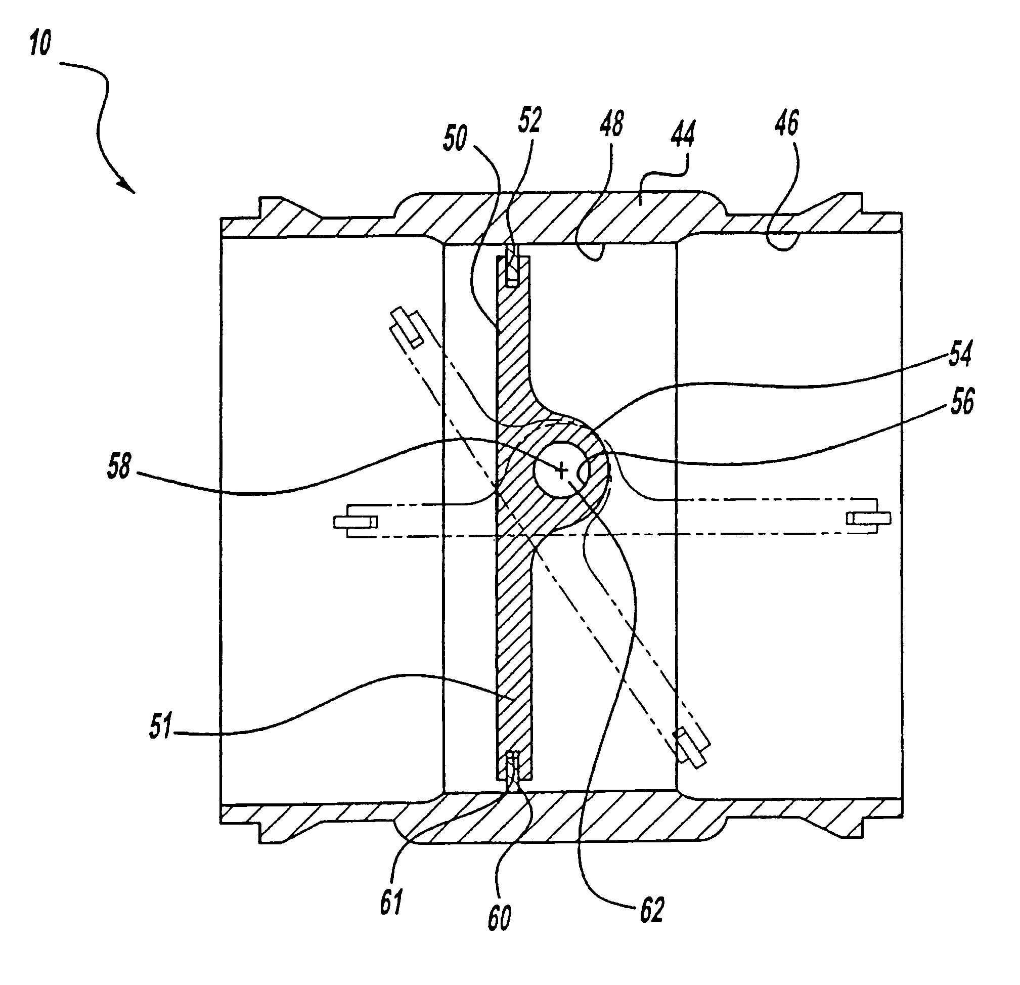
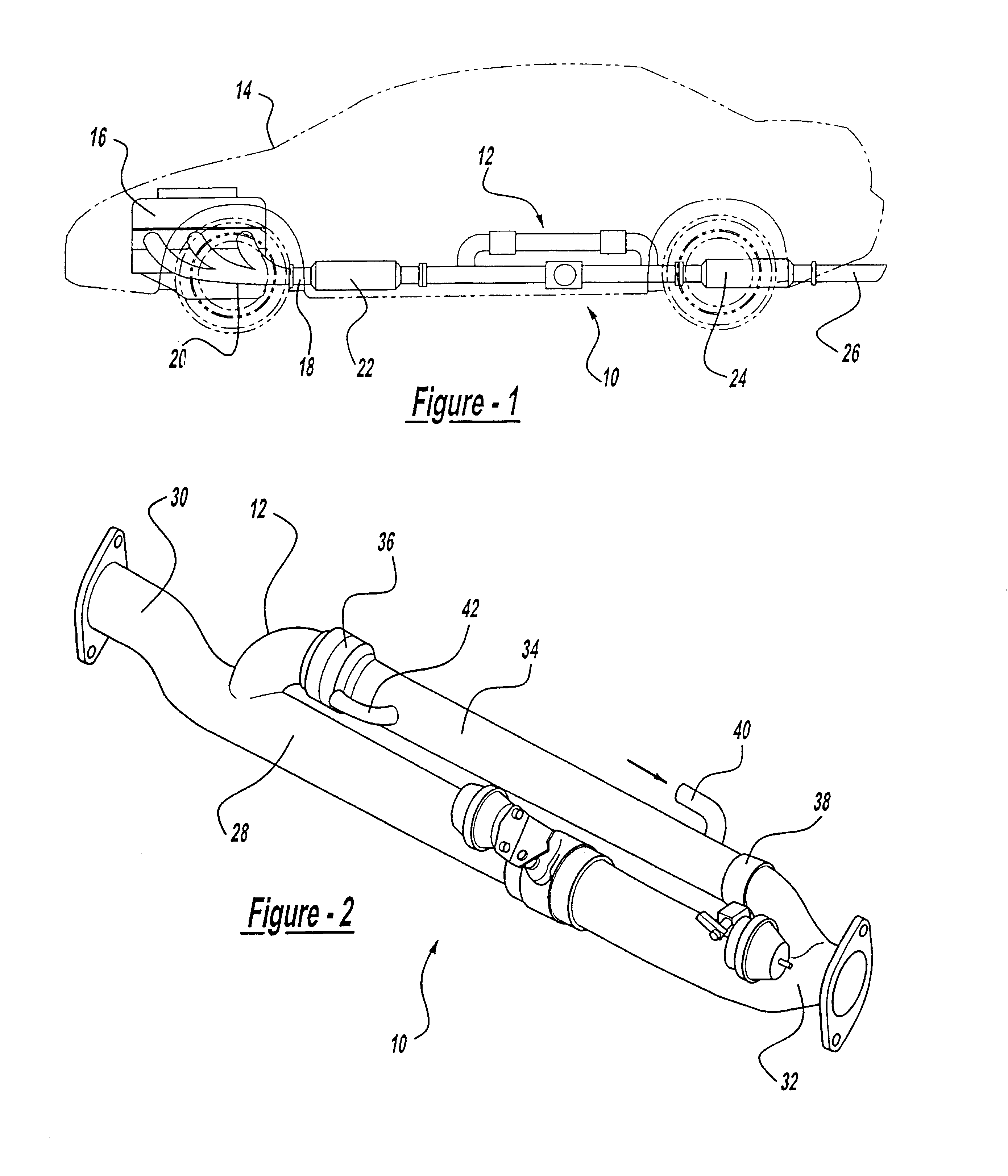
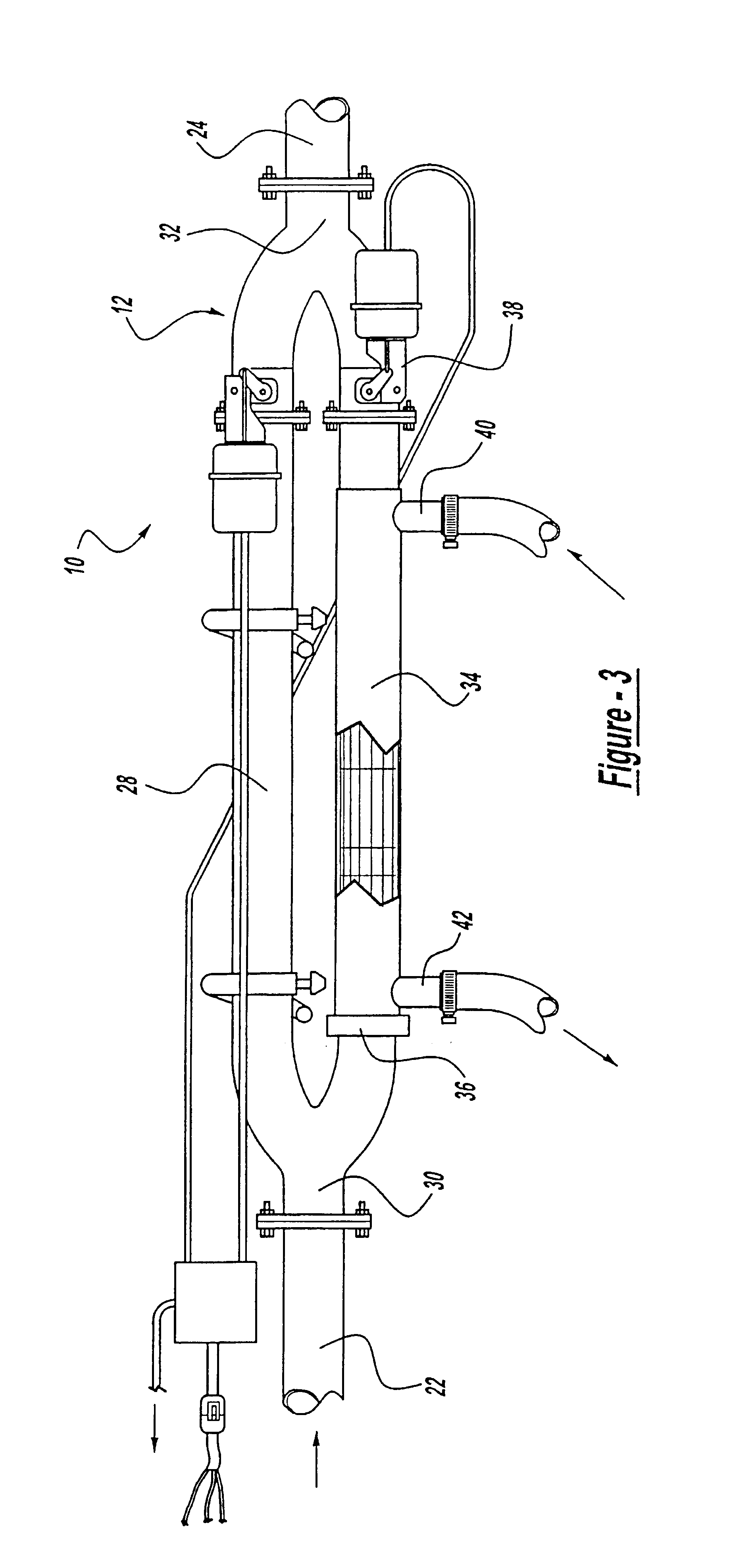
Referring to the drawings and in particular FIGS. 1 through 3, one embodiment of an exhaust valve 10, according to the present invention, is illustrated for an exhaust heat recovery system, generally indicated at 12, in a motor vehicle 14. The motor vehicle 14 includes a combustion engine 16 and an exhaust system 18 connected to the engine 16. The exhaust system 18 includes an exhaust manifold 20 connected to the engine 16 and a catalytic converter 22 connected to the exhaust manifold 20. In this embodiment, the exhaust heat recovery system 12 is connected to an exit end of the catalytic converter 22 to provide supplemental heat to an occupant compartment (not shown) of the motor vehicle 14 from the heat of the exhaust gases from the engine 16. The exhaust system 18 further includes a muffler 24 connected to an exit end of the exhaust heat recovery system 12 and a tailpipe 26 connected to the muffler 24. It should be appreciated that, except for the exhaust heat recovery system 12,...


PUM


Abstract

An exhaust valve (10) includes a housing (44) having a passageway (46) extending axially therethrough. The exhaust valve (10) also includes a rotatable butterfly plate (50) disposed in the passageway (46) of the housing (44) and having an annular groove (52) in a periphery thereof. The exhaust valve (10) further includes a ring seal (60) disposed in the groove (52) and being radially compressible and expandable for engagement and disengagement with the housing for opening and closing the passageway (46) to allow and prevent exhaust gases flowing therethrough.

Description

1. Field of the InventionThe present invention relates generally to exhaust heat recovery systems for motor vehicles and, more specifically, to an exhaust valve for a combustion engine in a motor vehicle.2. Description of the Related ArtIt is known to provide a supplemental heating device such as an exhaust heat recovery system for a motor vehicle to harness waste heat from exhaust gases to heat air for an occupant compartment of the motor vehicle. Generally, the exhaust heat recovery system includes an exhaust pipe mounted to an exit end of a catalytic converter of an exhaust system of the motor vehicle and a heat exchanger mounted to and in parallel with the exhaust pipe. The exhaust heat recovery system also includes a by-pass valve to control the flow of exhaust gases from the catalytic converter through either the exhaust pipe or the heat exchanger. The exhaust heat recovery system includes a back-pressure valve in series with the heat exchanger to prevent exhaust gases from re...

Claims


Application Information

Patent Timeline
IPC IPC(8): F01N3/28F01N3/08F01N3/20F02D9/10F02D9/04F02D9/08F02D9/00F16K1/226F16K1/228
CPCF01N3/0842F01N3/0878F01N3/2006F01N3/2053F01N3/2889F01N5/02F02D9/04F02D9/1015F02D9/1025F16K1/2261F16K1/228F01N2240/02Y02T10/16Y02T10/26Y02T10/12
Inventor RIM, DEAN JINKYU
Owner VISTEON GLOBAL TECH INC
Features
  • Generate Ideas
  • Intellectual Property
  • Life Sciences
  • Materials
  • Tech Scout
  • Unparalleled Data Quality
  • Higher Quality Content
  • 60% Fewer Hallucinations
Learn More