Hot sprue system for diecasting

a technology of diecasting and hot sprue, which is applied in the direction of molten metal conveying equipment, foundry moulding apparatus, melt-holding vessels, etc., can solve the problems of high energy loss, large amount of metal contained in the sprue and runner castings compared to the metal in the product, and high energy loss

Inactive Publication Date: 2004-06-08
HOTFLO DIECASTING
View PDF11 Cites 13 Cited by
  • Summary
  • Abstract
  • Description
  • Claims
  • Application Information

AI Technical Summary

Problems solved by technology

Though hot-chamber diecasting is very common, relatively trouble-free and can produce high quality product at high production rates, a major disadvantage of the technique is the large amount of metal contained in the sprue and runner castings compared with the metal in the product.
After detachment from the products, the sprue and runner castings are generally remelted and reused, but this represents high-energy losses and causes melt contamination.
Another significant disadvantage of conventional hot-chamber diecasting is the abrupt discontinuity in both section and direction in the melt path between the wide and widening sprue channel and the narrow and narrowing runner channel(s); a discontinuity which leads to turbulent and inefficient melt flow.
While both can pump shots of melt into cavities via sprue and runner systems, losses associated with the sprue and runner castings are much less with injection moulding.
While it has been suggested from time to time (see for example U.S. Pat. Nos. 4,304,544 and 4,795,126 to Crandell) that heated nozzles and hot-tips designed for injection moulding can be used for direct-injection diecasting, this has proved impractical.
The much higher melting po

Method used


Image

  • Hot sprue system for diecasting
  • Hot sprue system for diecasting
  • Hot sprue system for diecasting

Examples


Embodiment Construction

Having portrayed the nature of the present invention, two examples will now be described with reference to the accompanying drawings. However, those skilled in the art will appreciate that many variations and modifications can be made to the chosen examples without departing from the scope of the invention as defined by the following claims.

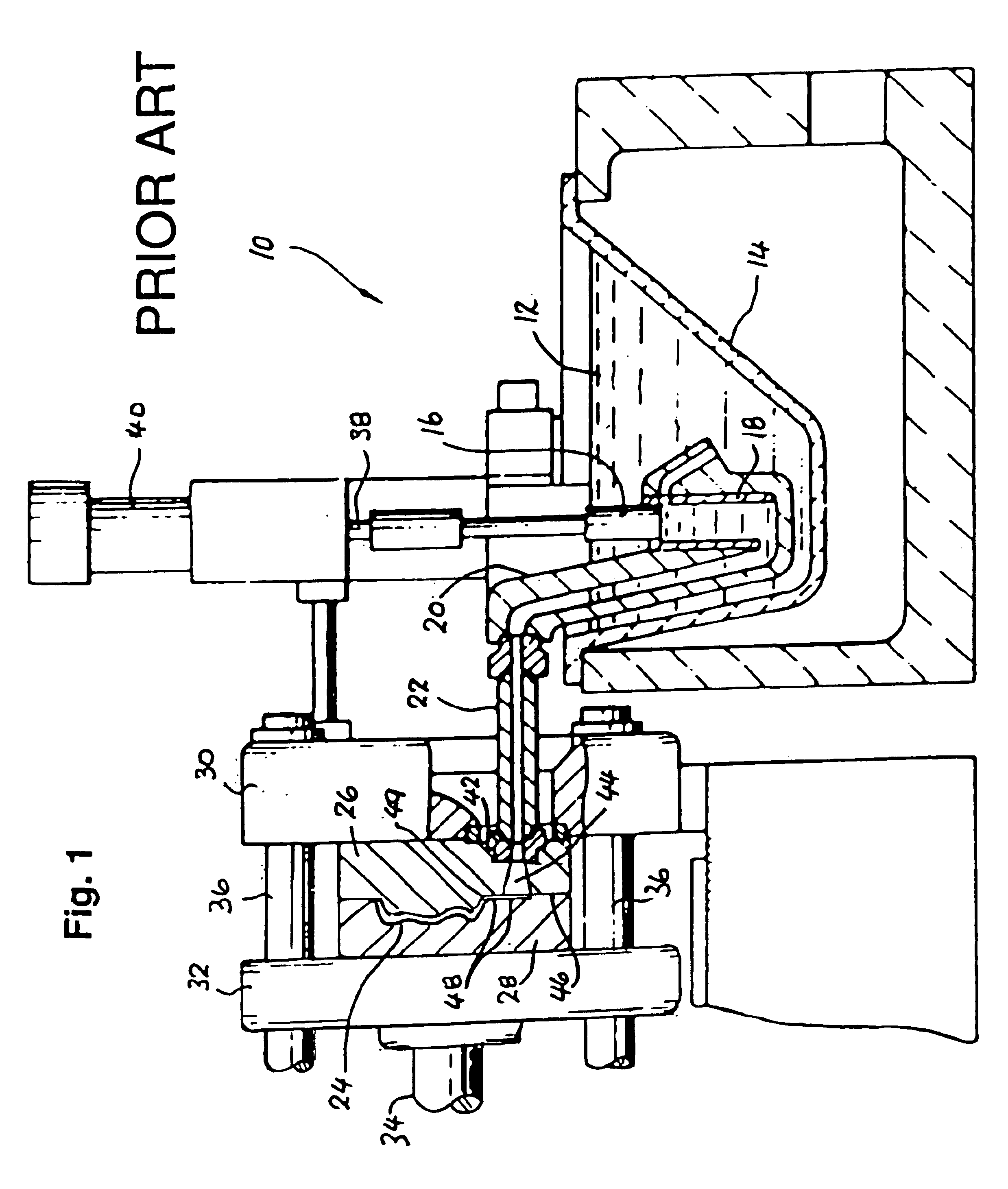
FIG. 1 is a part-sectional elevation of a typical prior art hot-chamber diecasting machine.

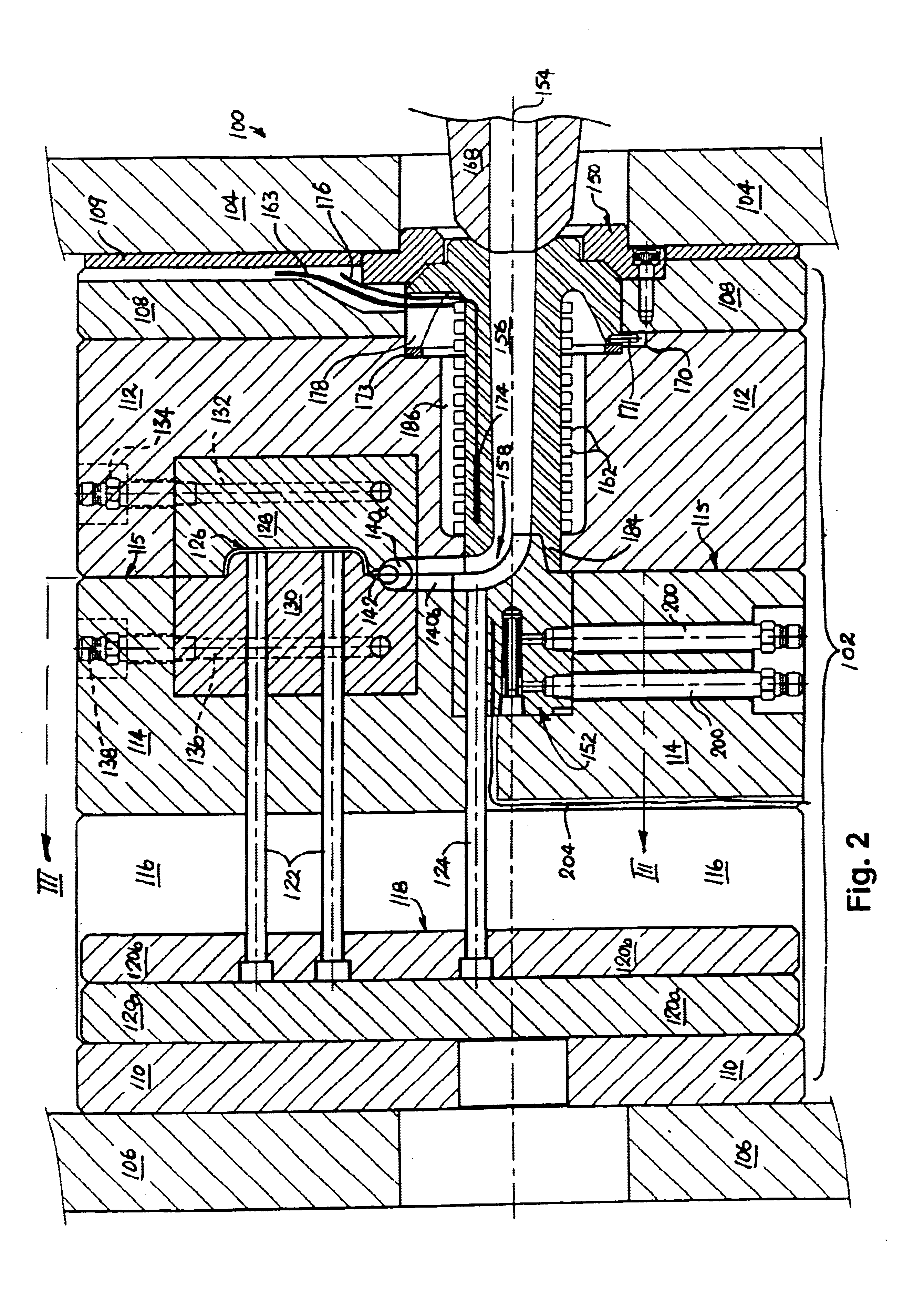
FIG. 2 is a diagrammatic sectional elevation of portion showing the die-set of a typical diecasting machine with sprue inserts formed in accordance with the first example of the present invention.

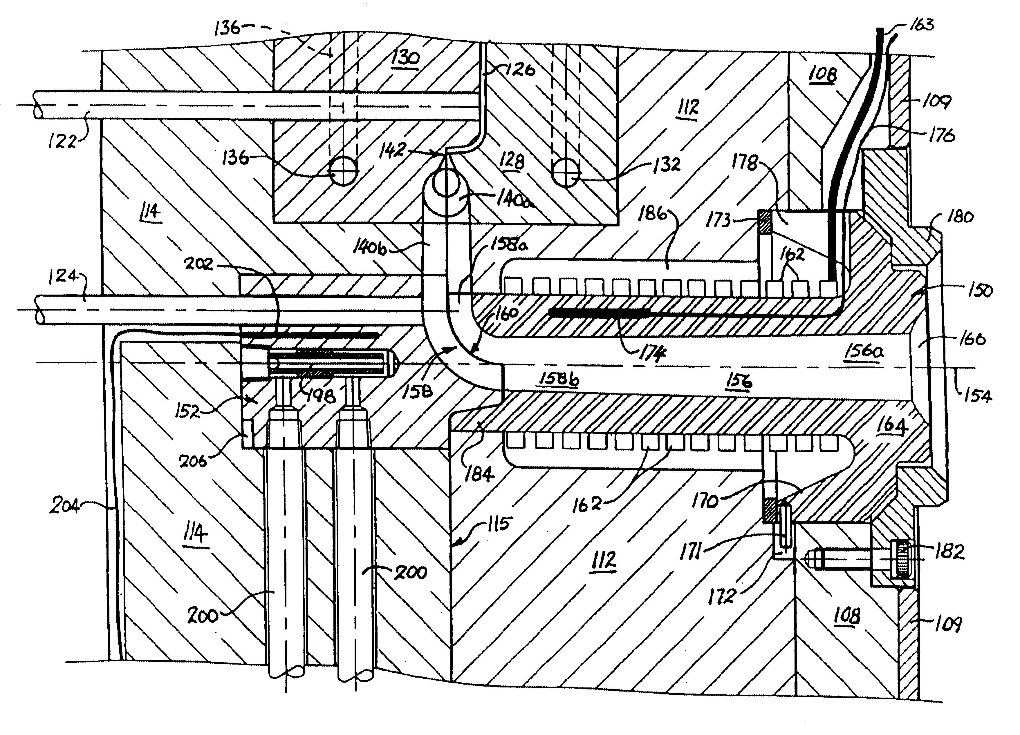
FIG. 3 is an enlarged view of portion of FIG. 2.

FIG. 4. is an enlarged plan view of portion of the die set of FIG. 2 taken on section line III--III of FIG. 2.

FIG. 5 is a perspective view of the sprue-body insert of FIGS. 2 and 4.

FIG. 6 is a perspective view of the sprue-tip insert of FIGS. 2, 3 and 4.

FIG. 7 is a sectional elevation of a die-set having a sprue and a...


PUM

PropertyMeasurementUnit
Angleaaaaaaaaaa
Temperatureaaaaaaaaaa
Pressureaaaaaaaaaa

Abstract

A sprue insert-set which substantially eliminates sprue castings and improves melt-flow in high-pressure hot-chamber diecasting. The insert-set consists of (i) a heated sprue body insert for mounting in the fixed dieblock of a die set and (ii) a cooled sprue tip insert for mounting in the moving dieblock of the die set. The body and tip inserts are mounted so that their inner ends mate with one another in the region of the die parting-line to conjointly form a curved transition channel that connects the sprue channel in the body insert with a runner channel formed along the parting-line of the die set. The temperatures of the body insert and the top insert can be controlled so that the freeze-point occurs in the transition channel and the melt in the sprue channel is able to run back into the machine nozzle at the end each shot, thereby eliminating sprue castings.

Description

This invention relates to high-pressure diecasting methods and apparatus, and more particularly, to hot sprue systems for use with hot-chamber, high-pressure diecasting.BACKGROUND TO THE INVENTIONThere is a very large installed base of hot-chamber, high-pressure, diecasting machines dedicated to the production of small die-cast products of zinc, lead, tin magnesium, aluminum and their alloys. FIG. 1 shows a typical machine 10 of this type. A pool of molten metal 12 is held in a heated pot 14 from which `shots` of melt are forced, by a plunger 16 working in a submerged cylinder 18, through a gooseneck 20 and an externally flame-heated connecting nozzle 22, into a cavity 24 formed between a fixed die 26 and a moving die 28. Fixed die 26 is mounted on a fixed platen 30 and moving die 28 is mounted on a moving platen 32 that is pressed toward the fixed platen by the piston 34 of a hydraulic or pneumatic ram, the clamping force being taken by tie-rods 36. When dies 26 and 28 are closed, ...

Claims


Application Information

Patent Timeline
IPC IPC(8): B22D17/22B22C9/06B22C9/08B22D17/20B22D17/02B22D17/32
CPCB22D17/2272
Inventor WILSON, GRAHAM LOUIS
Owner HOTFLO DIECASTING
Why Eureka
Try Eureka