
Bench with modular structure

a modular structure and bench technology, applied in the direction of convertible chairs, folding chairs, dismountable chairs, etc., can solve the problems of large installation cost, large installation space, and inconvenient use, and achieve the effect of small space, secure upright position, and time saving and efficien

Inactive Publication Date: 2004-06-08
VITRA PATENTE AG
View PDF12 Cites 27 Cited by
  • Summary
  • Abstract
  • Description
  • Claims
  • Application Information

AI Technical Summary

Benefits of technology

In view of the imperfections described above, the invention is based on the object of proposing a bench of this type which can be constructed in a modular manner and has a longitudinal beam in the underframe, and whose functional units, namely the seat panels, backrests, armrests and tabletops, can be arranged in a freely variable manner without having to follow a grid of clamping elements provided in a fixed manner. The intention is to enable the bench to be constructed on the basis of releasable connections, so that the installation at the location of use can be undertaken in a time-saving and efficient manner. All of the abovementioned functional elements, and also the feet and supports, are to take up as little space as possible during storage and transportation. The subsequent modification and the maintaining of constructed benches must be simple to implement. Obviously, the bench has to ensure a secure upright position even when loaded unevenly. Finally, the intention is to be able to produce the bench in an efficient manner, at favorable costs, while also satisfying individual customer's wishes. In the long run, the construction has to permit a design corresponding to contemporary tastes.
The bench according to the invention allows a variable configuration thereof with armrests and tabletops which can be fitted next to the seat panels and backrests, without having to be tied down to a grid consisting of fixed clamping elements or weld points. The cutting of the longitudinal beam to the required length from a profiled rod, the entire installation and modification of the bench and also the interchange of functional units for maintenance purposes at the location of use can take place directly and efficiently. The design phases therefore are simplified. During the delivery and storage of the unassembled functional units of a bench, decidedly less space is required than for a bench which has already been assembled. The saving on space multiplies if a relatively large area, for example an airport terminal, is to be equipped with a large number of benches.

Problems solved by technology

With current requirements for the lowest possible outlay on installation, great variability in the equipment options, space-saving volume while in transportation and saving on weight, the bench described above does no longer fulfill all demands.
The brackets used as supports for the seat panels and the backrests, and also the feet are thus relatively bulky and material-intensive.
The result is therefore either a fairly high and time-consuming outlay on installation at the location of use of the benches or the premanufactured benches have to be transported along the delivery route as voluminous pieces of equipment.
The brackets are designed for holding seat panels and backrests, so that in the case of benches used in zones for brief stops, the backrests cannot be dispensed with.
It would likewise be problematical to leave out the armrests, which are always provided, for brief stops.

Method used


Image

  • Bench with modular structure
  • Bench with modular structure
  • Bench with modular structure

Examples


Embodiment Construction

The detailed description of an exemplary embodiment of the bench according to the invention is given below with reference to the attached drawings. Possible modifications which are worth mentioning are listed in the annex to the description.

The following statement applies to the entire further description: if reference numbers are contained in a figure for the purpose of diagrammatical unambiguousness, that are not explained in the directly appended text of the description, reference is made to where they are mentioned in the preceding or subsequent description of the figures. In the interests of clarity, repeated designation of components in subsequent figures is generally dispensed with, as long as it can unambiguously be recognized diagrammatically that these are "recurring" components.

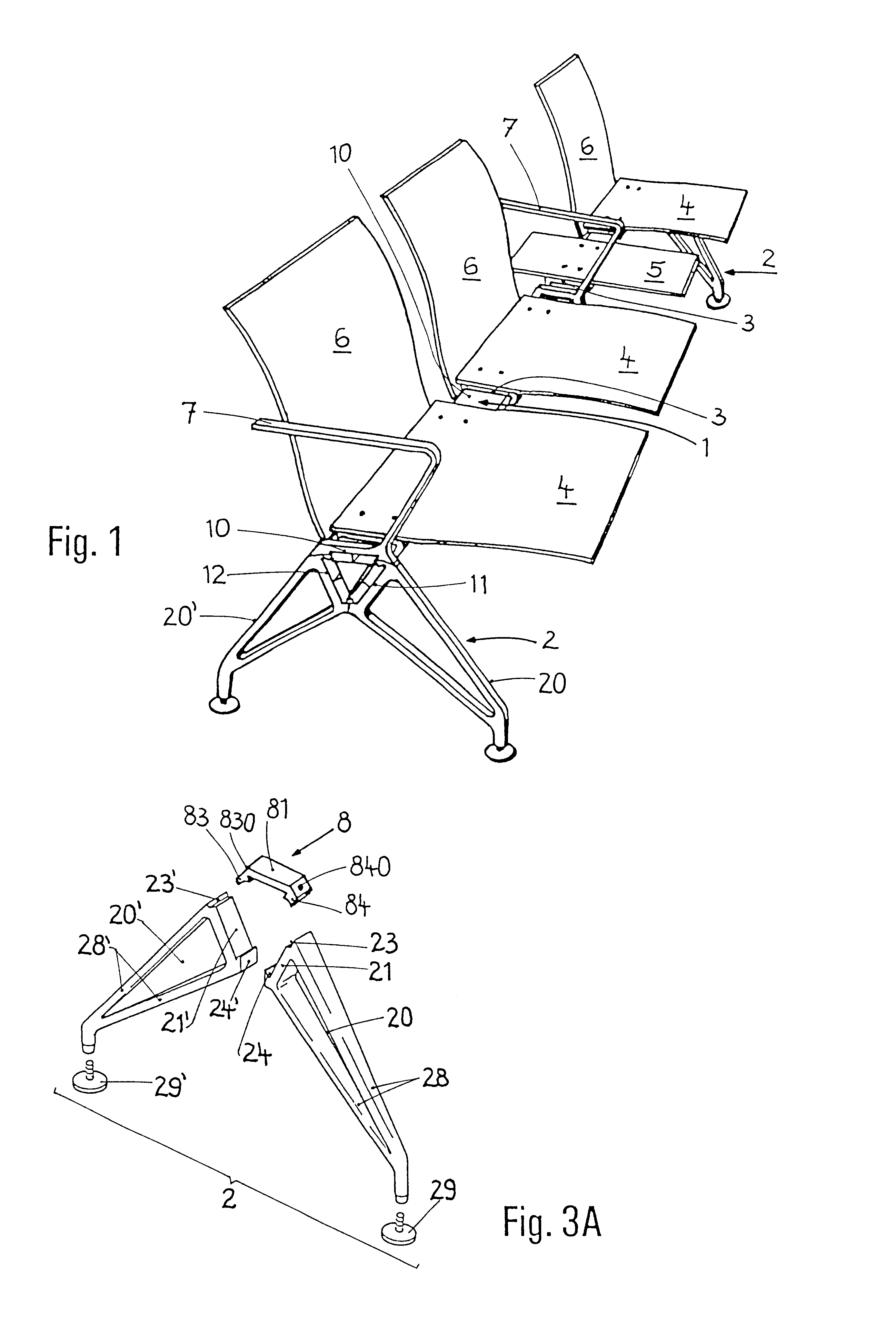
FIG. 1

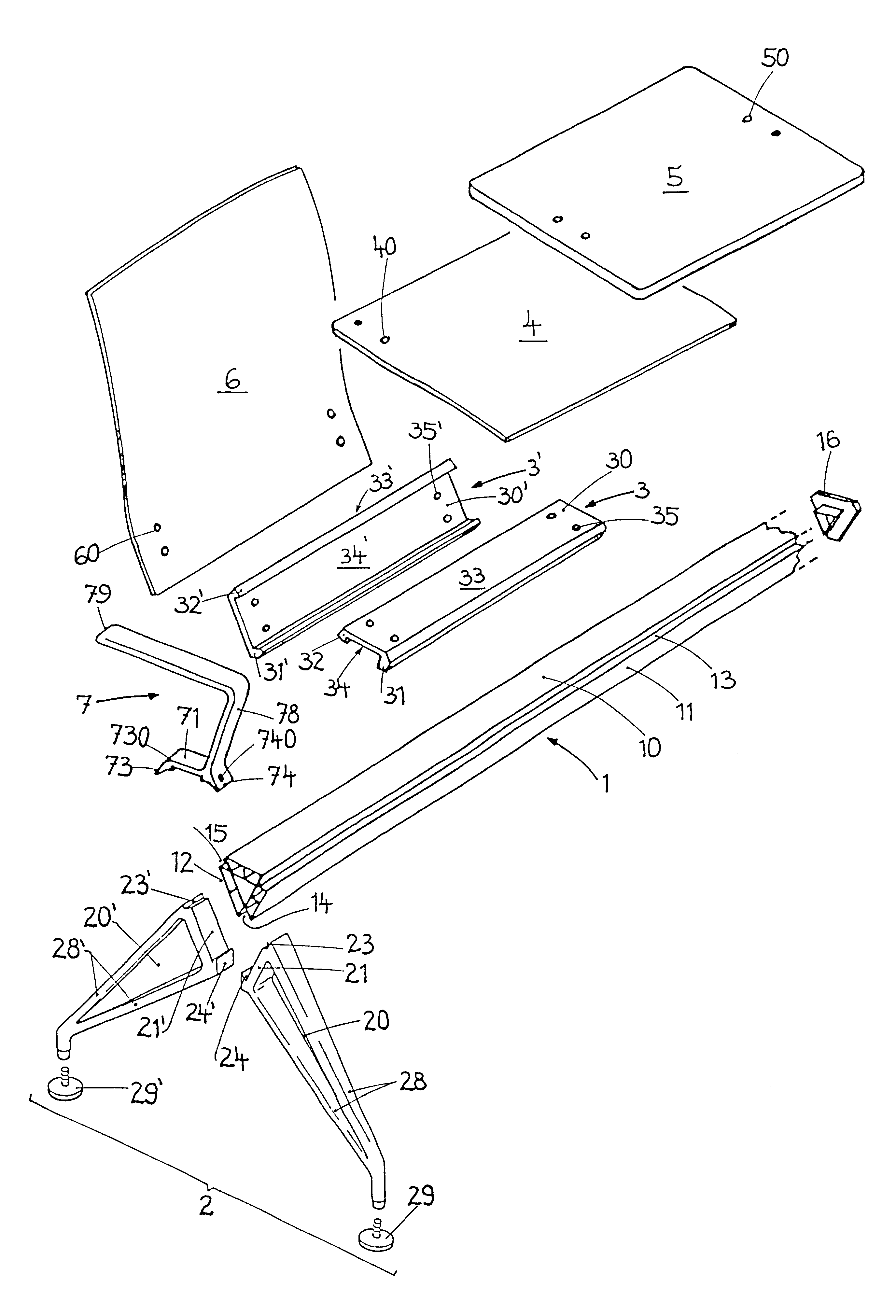
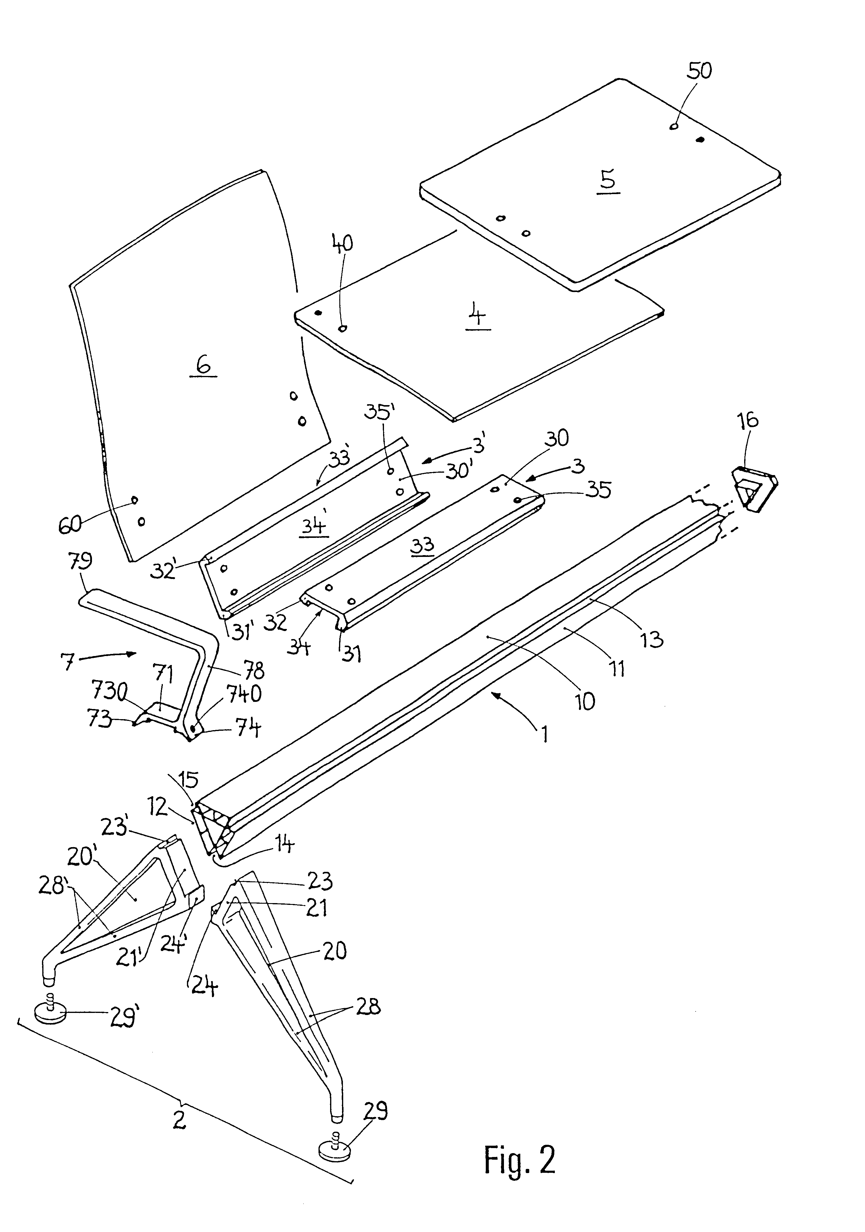
As the underframe, the bench has a longitudinal beam 1 which extends horizontally and over the entire length of the bench onto which longitudinal beam at least two feet 2 are joined. The long...


PUM


Abstract

A bench having a modular structure and comprising several seats, which rest on a longitudinal beam supported on at least two feet. An individual seat is formed by a seat panel which can be complemented by a backrest and lateral armrests, as well as tabletops. Benches of this kind can be used, for example, in airports and ferry terminals as well as long-distance train stations. The seat panels, backrests and tabletops are removably fixed to the longitudinal beam by the use of retaining plates. The feet and armrests are removably fixed directly to the longitudinal beam. The longitudinal beam extends along the full length of the bench, consists preferably of a double-walled aluminum hollow profile and has a regular, triangular cross-section with three longitudinal side faces as well as longitudinal grooves, situated in the area of the edges. The retaining plates are pieces of U-shaped rail sections cut to the required length. A retaining plate connected to a seat panel or a table top rests on the upper, first side face of the longitudinal beam, while retaining plate connected to the backrest contacts the rear surface of the longitudinal beam. The principal advantages of the bench are its variable configurations, the fact that it can be assembled at the place of use and that functional units can be easily replaced. Considerably less transport space is required for the delivery of unassembled functional units.

Description

FIELD OF USE OF THE INVENTIONThe invention relates to a bench which can be constructed in a modular manner and has a plurality of seats resting on an underframe. The individual seat has a seat panel which can be supplemented by a backrest and lateral armrests. Tabletops can be fitted on the outside or within the bench. Benches of this type are used, for example, in airports and ferry terminals and also in mainline railroad stations.PRIOR ARTThe "vitra.RTM.--CLASSICS--EAMES COLLECTION" brochure of Vitra.RTM. GmbH, Weil am Rhein / Germany, 1 / 86, shows a bench whose underframe consists of a longitudinal beam in the form of a T profile and two feet placed on the ground. The horizontal limb of the T profile lies upward, while the centrally adjoining vertical limb points downward. The feet are screwed onto the outer flanks of the bench or in the vicinity of these outer flanks, grip, with their upwardly open fork, under the T profile and in each case have two extension arms extending transve...

Claims


Application Information

Patent Timeline
Patent Type & Authority Patents(United States)
IPC IPC(8): A47C11/00A47C13/00A47C4/00A47C4/02
CPCA47C4/02A47C4/03A47C11/005A47C13/005
Inventor FOSTER, NORMAN
Owner VITRA PATENTE AG
Learn More