
Cellular radio communications system

Inactive Publication Date: 2004-06-08
MICROSOFT TECH LICENSING LLC
View PDF13 Cites 215 Cited by
  • Summary
  • Abstract
  • Description
  • Claims
  • Application Information

AI Technical Summary

Benefits of technology

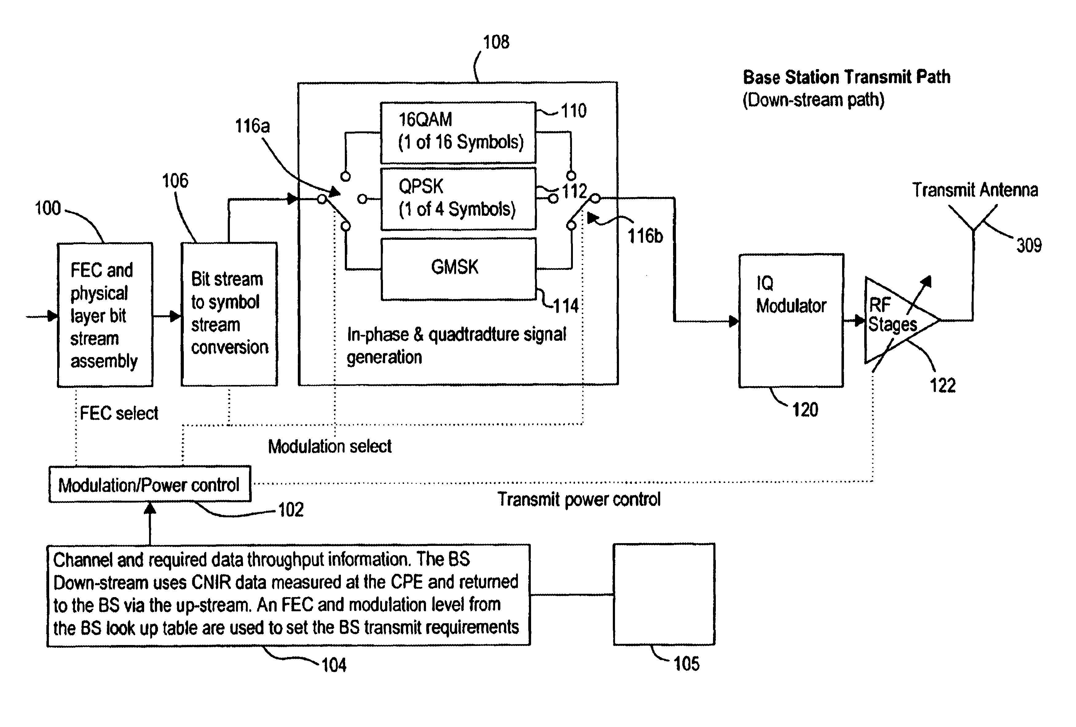
The present invention seeks to provide an improved cellular radio communication system which uses adaptive modulation and which can provide transmission links having optimised data rates with low bit error rates dependent on the prevailing transmission conditions, while maintaining the links in the poorest transmission conditions. Because links can be maintained in poor transmission conditions the present invention can enable operation over longer distance transmission links.

Problems solved by technology

The performance of wireless access communication systems is prone to dynamic degradation, ie. time variant degradation, due to changing environmental conditions.
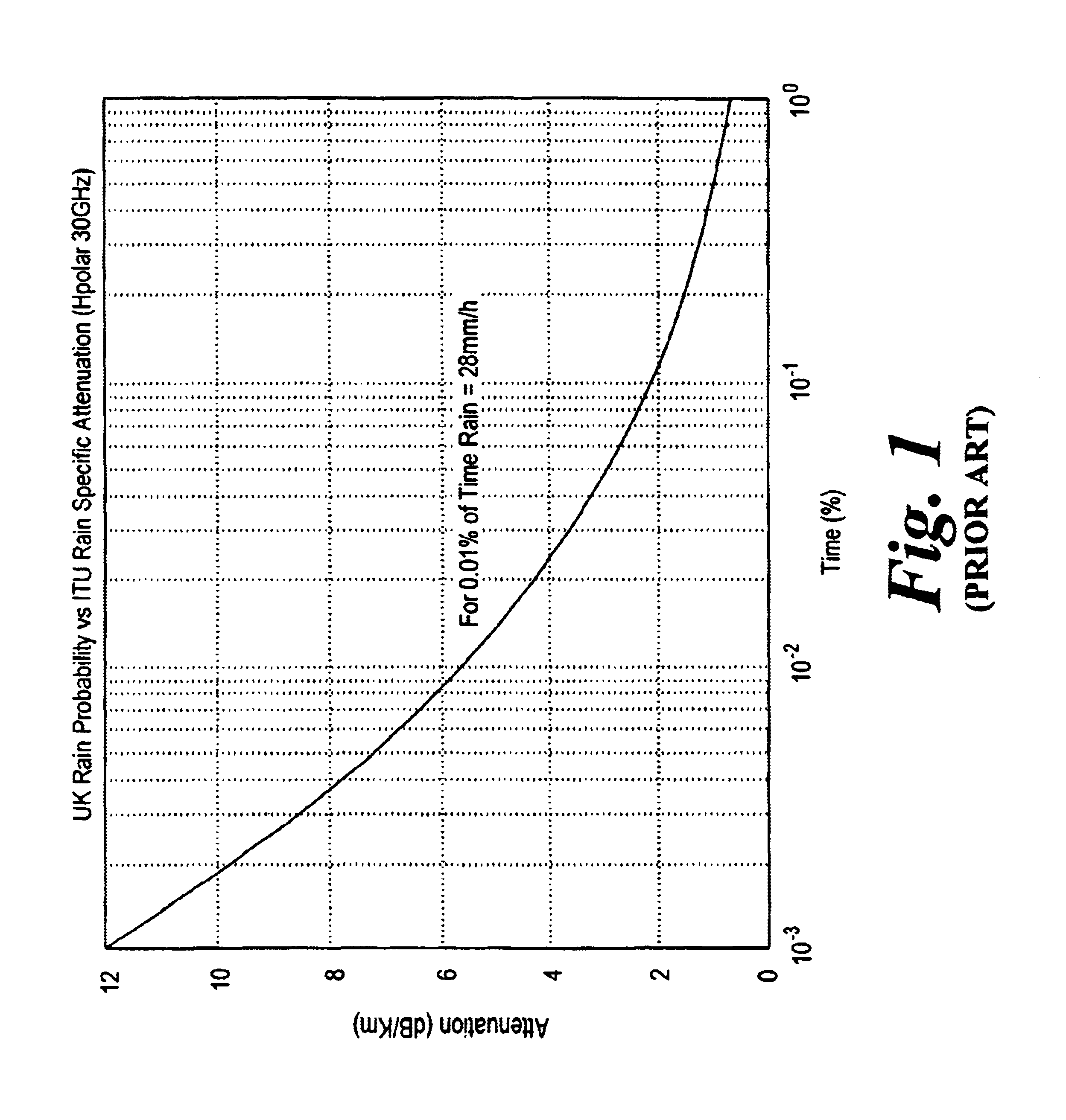
Wireless transmissions in the frequency range from 10 to 50 GHz are particularly prone to dynamic degradation resulting from rain and from the growth and movement of foliage located in the transmission path.
However, designing such systems for worst case environmental conditions in this way results in low rates of data transmission.
However, for very poor transmission conditions or for transmissions over longer distances a break in communication can occur.
This limits the output power of the amplifier, thus limiting the power of the signal that can be transmitted over the transmission link.
In poor transmission conditions, more data will have to be re-sent and so data rates will be low.
However, this method has a degree of transmission delay inherent within it which may not be appropriate for all multimedia services.
It is also inefficient in terms of the amount of uplink or downlink resource used for services requiring a low bit error rate.

Method used


Image

  • Cellular radio communications system
  • Cellular radio communications system
  • Cellular radio communications system

Examples


Embodiment Construction

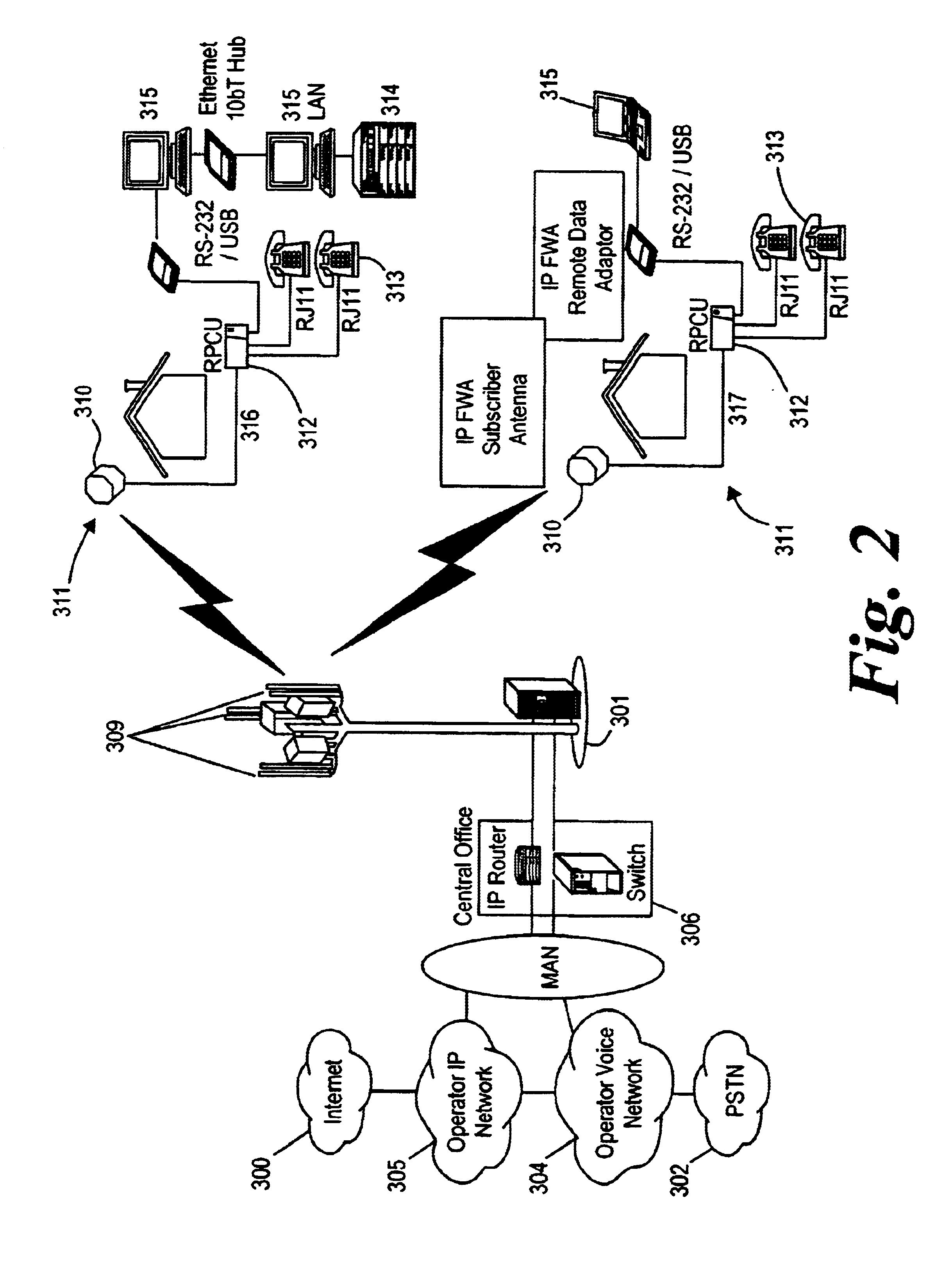
FIG. 2 shows a fixed wireless access architecture suitable for use in a cellular radio communication system according to the present invention. The architecture comprises a fixed wireless access base station (301) which can transmit radio frequency signals to a plurality of CPEs (Customer Premise Equipments) (311) within a localised area or cell. The base station has an array of antennas (309) for transmitting signals to and receiving signals from antennas (310) which form part of the CPEs (311). The antennas (310) located at a subscriber's premises and the base station antennas (309) are generally located in a raised position at some distance from the ground in order to reduce the effect of obstacles in the transmission paths between the base station and the CPEs. In this way a line of sight (LOS) or near line of sight (NLOS) transmission link can be achieved between the base station and each CPE within the cell. The CPE antennas (310) are each connected to associated remote power ...


PUM


Abstract

A cellular radio communication system is provided for transmitting data over a plurality of transmission links. The system includes means for generating a modulated signal by applying a constant amplitude envelope modulation scheme to data to be transmitted across poor quality transmission links and amplifier means for non-linearly amplifying the modulated signal. The system can additionally include means for generating a second modulated signal by applying an amplitude dependent modulation scheme to data to be transmitted across higher quality transmission links and amplifier means for linearly amplifying the second modulated signal. Using a constant amplitude envelope modulation scheme, such as GMSK or MLCAM for poorer quality links means that for these links signals can be amplifier non-linearly at higher gains.

Description

The present invention relates to a cellular radio communication system. In particular the present invention relates to a broadband wireless access system suitable for the delivery of multi-media services.BACKGROUND OF INVENTIONThere is a growing demand for broadband wireless access systems which can deliver the high data rates required for the provision of multi-media services. Such wireless access systems operate within licensed frequency bands. Accordingly, these systems are continually developing to carry more data across the limited frequency band allocated to them. Pressure for this development is two fold. Firstly, there is increased demand for multi-media services from subscribers to the system. Secondly, revenue for the network operator will increase as billing is calculated on a per byte of information delivered basis as opposed to on a per second basis.The performance of wireless access communication systems is prone to dynamic degradation, ie. time variant degradation, du...

Claims


Application Information

Patent Timeline
IPC IPC(8): H04L1/00H04L27/34H04L27/20
CPCH04L1/0003H04L27/2017H04L27/34H04L2001/0096
Inventor DALY, NEIL
Owner MICROSOFT TECH LICENSING LLC
Learn More