
Aircraft service pit lid hinge

Inactive Publication Date: 2004-06-15
CAVOTEC ACQUISITION US
View PDF13 Cites 36 Cited by
  • Summary
  • Abstract
  • Description
  • Claims
  • Application Information

AI Technical Summary

Benefits of technology

There is really no laterally acting force of any consequence that would tend to push the hinge pin longitudinally within the straight bore within the structure of the lid frame. Nevertheless, the upwardly projecting and surrounding rim of the pit liner effectively blocks the bore opening or openings in the peripheral edge of the frame, and thereby prevents the hinge pin from shifting in either direction along the longitudinal axis of lid rotation once the lid assembly has been seated in the pit liner.
This objective can be achieved with the pit lid assembly of the invention by forming the pit lid with a perimeter having a seal mounted thereon. The seal forms an enclosed loop that resides in a horizontal sealing plane that seals the pit access opening throughout its entire circumference when the pit lid rests upon the bearing ledge. The hinge pin and the horizontal bore into the structure of the pit frame in which the hinge pin is located, reside in a horizontal plane that is located between the sealing plane and the deck. By locating the hinge pin and the axis of hinge rotation between the sealing plane and the deck, the seal will leave contact with the frame with the first movement of lifting the lid from a closed position. There is therefore very little friction between the seal and the frame as the pit lid is opened and closed. Nevertheless, since the seal does establish contact with the frame at the final instant of closure, the necessary moisture sealing of the access opening is achieved.
Preferably the hinge pocket has an inclined end wall remote from the access opening. The hinge pocket end wall extends between the pocket side walls and is inclined at an obtuse angle, preferably about one hundred twenty degrees, relative to the deck of the pit lit assembly frame. The hinge leaf has a flat upper surface the meets the hinge pocket end wall in surface-to-surface contact when the pit lid is rotated upwardly about the axis of lid rotation to a maximum extent away from the access opening. This construction has several advantages.
The pit lid hinge leaf must have a thickness less than the thickness of the pit lid itself. By making the hinge leaf with a flat upper surface and by locating the hinge pin such that the flat upper surface of the hinge leaf meets the hinge pocket end wall in surface-to-surface contact throughout, a line of stress across the neck of the hinge leaf is avoided. Such a line of stress could result in a fracture of the hinge leaf with repeated use over time, breaking it at its junction with the pit lid. The transition between the hinge leaf and the pit lid is preferably curved so as to provide further strength and avoid a potential fracture line across the hinge leaf.
Another advantage of constructing the hinge leaf and the hinge pocket with flat surfaces that meet in face-to-face contact is that when the pit lid is opened, the flat upper surface of the hinge leaf approaches the hinge pocket end wall in such a manner as to squeeze out debris that may have collected in the hinge pocket between the inclined end wall and the hinge leaf. At airports there is a very significant amount of airport dirt formed of rubber, weeds, and jet fuel. This material accumulates in virtually any recessed surface at the airport, and tends to collect in crevices and cracks. Consequently, there is a considerable likelihood that airport dirt will collect in the hinge pocket at the hinge axis where the hinge leaf is connected by the hinge pin to the pit lid frame.
Preferably the surface of the hinge leaf is flat and meets the end wall surface of the hinge pocket in face-to-face contact throughout as the pit lid is opened to a maximum position at an obtuse angle relative to the plane of the deck of the frame. By constructing the hinge assembly so that the upper surface of the hinge leaf meets the end wall of the leaf pocket in a surface-to-surface contact, a self-cleaning hinge joint is created. That is, as the hinge leaf opens and the angle between the approaching upper surface of the hinge leaf on the stationary end wall of the hinge pocket grows smaller, the airport dirt is squeezed out of the diminishing space between the hinge leaf and the pocket end wall. Since many aircraft service pit lid assemblies remain closed and are not accessed for long periods of time, this self-cleaning feature is important, since it prevents the hinge joint from becoming jammed after a prolonged period of nonuse.

Problems solved by technology

While quite convenient and easy to construct, upwardly projecting hinge assemblies have significant disadvantages.
The are highly susceptible to damage by snow plows and ground support vehicles traveling over the pit lit assemblies.
While locating the pit lid hinge assembly within the pit itself avoids the problems associated with exposed pit lid hinge assemblies, conventional hinge arrangements of this type present other problems.
Conventional pit lid hinge assemblies that are located within the confines of a pit are expensive and relatively complex in construction.
They typically involve spring mechanisms and multiple lever arms that can become fouled or broken over time.
Furthermore, the use of conventional subsurface hinge assemblies located within the confines of the pit itself presents an obstruction to access to the lines terminating within the pit.
A portion of the access opening is necessarily blocked by such a hinge mechanism, thus making it more difficult for ground servicing personnel to enter or reach down into the pit.
Also, these obstructions can cause injury to ground servicing personnel as then enter or leave the pit through the access opening.
In the absence of such a seal, the pit is likely to fill up with dirt and debris that would wash down into the pit access opening during rainy weather or with melting snow.
Such a line of stress could result in a fracture of the hinge leaf with repeated use over time, breaking it at its junction with the pit lid.
At airports there is a very significant amount of airport dirt formed of rubber, weeds, and jet fuel.
This material accumulates in virtually any recessed surface at the airport, and tends to collect in crevices and cracks.
Consequently, there is a considerable likelihood that airport dirt will collect in the hinge pocket at the hinge axis where the hinge leaf is connected by the hinge pin to the pit lid frame.

Method used


Image

  • Aircraft service pit lid hinge
  • Aircraft service pit lid hinge
  • Aircraft service pit lid hinge

Examples


Embodiment Construction

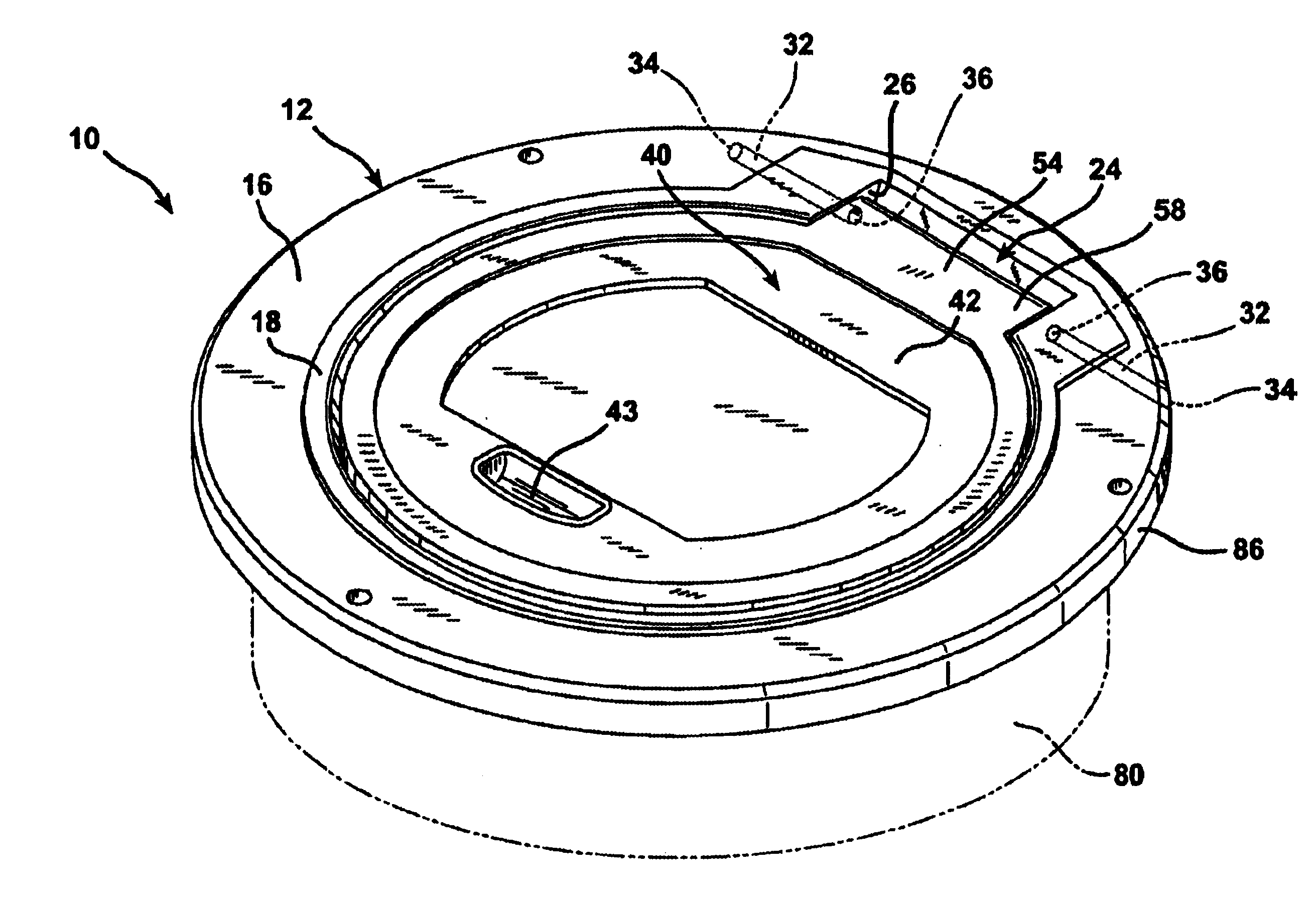
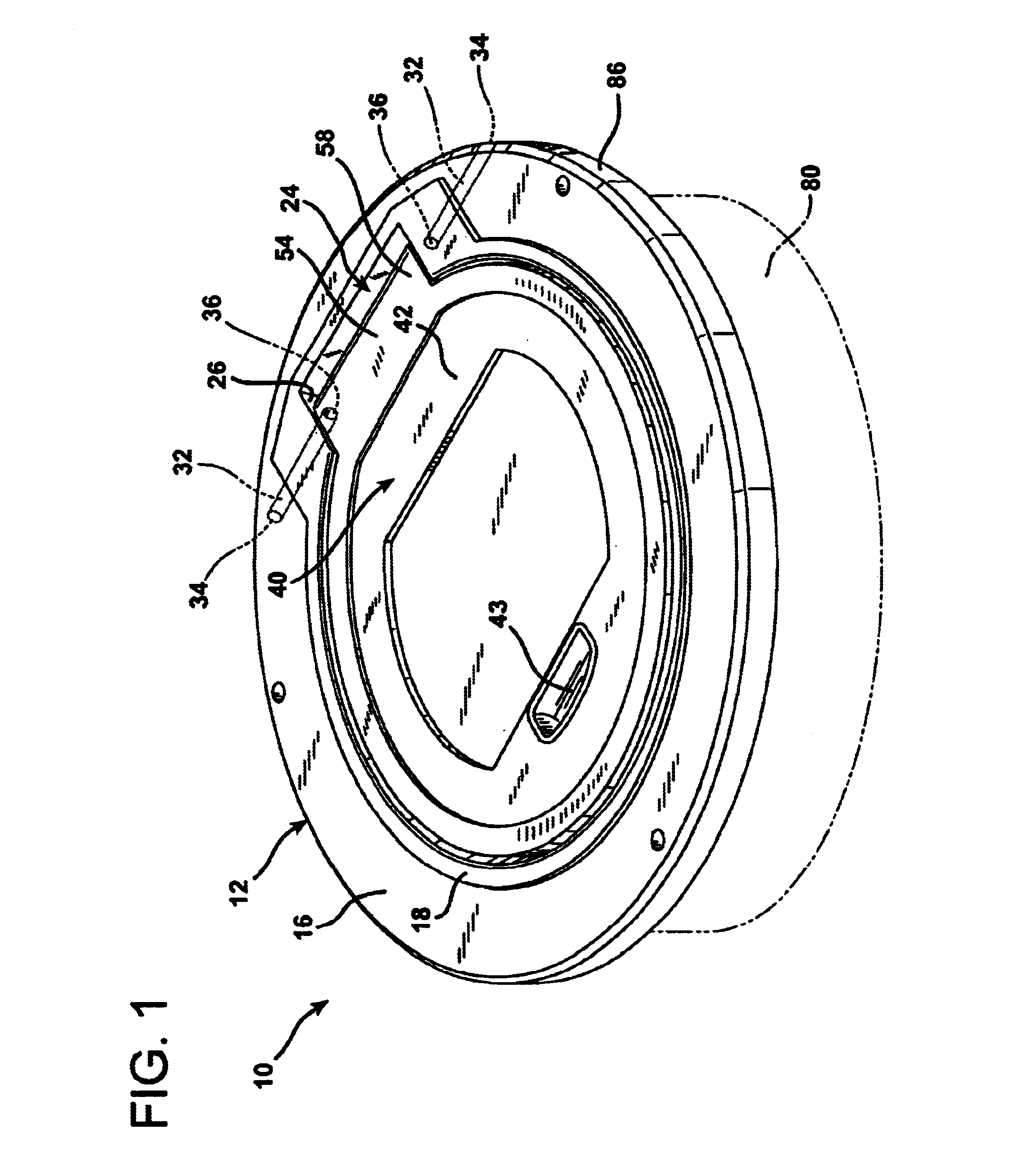
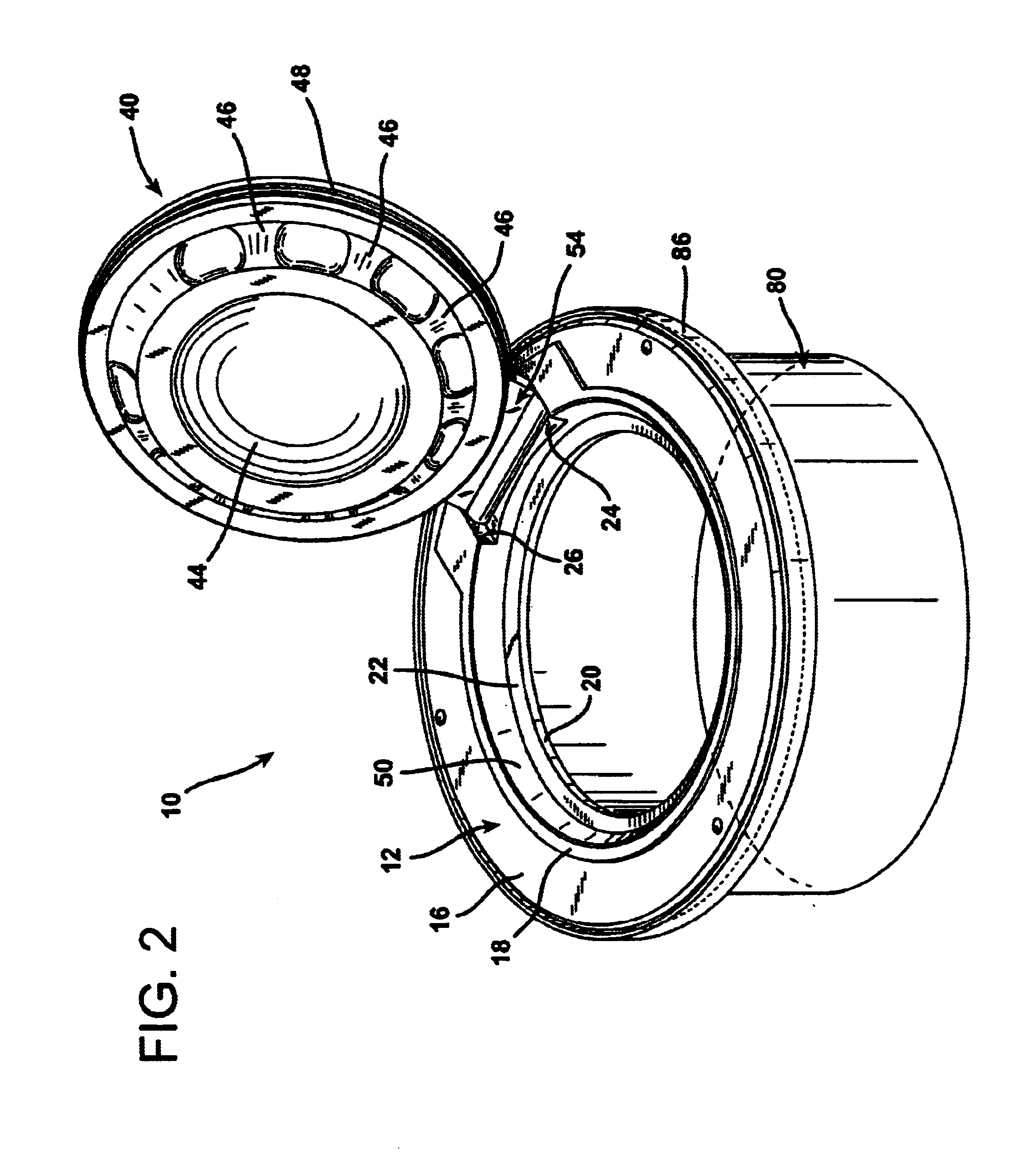
FIGS. 1 and 2 illustrate an aircraft service pit lid assembly 10 according to the invention. The pit lid assembly 10 is comprised of a lid frame 12 adapted for installation into a surface across which aircraft travel. In the embodiment illustrated in FIGS. 1 and 2, the lid frame 12 is of a circular, annular configuration, although pit lid frames are also formed in square and rectangular configurations as well. The lid frame 12 defines a perimeter with a short, upright, cylindrical wall or edge 14, visible in FIG. 3. The structure of the lid frame 12 also forms a flat, horizontal deck 16 and a raised ring 18 that extends about the inner perimeter of the deck 16 and which forms a water dam obstruction that inhibits the flow of water from the deck 16 down into a central, circular access opening 20.

The access opening 20 is encompassed within a low, annular, upwardly facing peripheral bearing ledge 22 surrounded by and set beneath the deck 16. A slightly frustoconical-shaped wall surface...


PUM


Abstract

A pit lid assembly is formed for a subsurface aircraft servicing pit and includes a lid frame formed with a flat, upper deck, a pit access opening surrounded by the deck, and a hinge pocket defined in the structure of the frame. The hinge pocket extends radially outwardly from the pit access opening and defines mutually opposing and mutually parallel pocket side walls. The pocket has a floor and an end wall slopes upwardly from the pocket floor at an obtuse angle relative to the surrounding flat deck of the frame. A pit lid is seated in the frame upon a bearing ledge formed about the periphery of the access opening. The pit lid has a hinge leaf projecting outwardly away from the access opening. Straight, narrow, linear bores are defined through the structure of both the hinge frame and the hinge leaf. These bores are in coaxial alignment with each other and reside in a horizontal plane located beneath the level of the flat, upper deck of the structure of the frame and above the level of a moisture barrier seal set into the underside of the pit lid. A hinge pin is inserted into the coaxially aligned bores in both the hinge frame and the hinge leaf. The structure of the hinge pin extends entirely through the hinge leaf and into the adjoining structure of the hinge frame. The pit lid may thereby be raised and lowered by rotation about the hinge pin, which is located beneath the surface of the surrounding deck of the frame.

Description

1. Field of the InventionThe present invention relates to a heave duty hinge for an aircraft service pit lid assembly that is used to provide access to subsurface pits located beneath airport runways, docking areas, and other surfaces across which aircraft travel.2. Description of the Prior ArtAt airports and airfields throughout the world, aircraft ground support electricity, air conditioning, fuel, and other aircraft servicing necessities are provided from pits located beneath the surfaces across which the aircraft travel. These pits provide subsurface terminations for aircraft servicing facilities such as fuel lines, electrical power supply lines, air conditioning ducts, and other auxiliary services which are provided to aircraft that are on the ground. The use of subsurface pits serves to reduce the congestion of motorized vehicles and lines running across the aircraft servicing areas that would otherwise exist.Aircraft servicing pits typically take the form of hollow, fiberglas...

Claims


Application Information

Patent Timeline
IPC IPC(8): E02D29/14E02D29/12
CPCE02D29/14E02D29/1463
Inventor PETERSEN, CRAIG A.
Owner CAVOTEC ACQUISITION US
Learn More