Method for tensioning and positioning a fiber optic cable

a technology of fiber optic cables and positioning devices, applied in the field of communication, can solve the problems of extremely demanding grating period tolerance of optical communication equipment, very small diameter of glass optical fibers of fiber optic cables, and inconsistent grating period

Inactive Publication Date: 2004-06-22
CIENA
View PDF4 Cites 13 Cited by
  • Summary
  • Abstract
  • Description
  • Claims
  • Application Information

AI Technical Summary

Problems solved by technology

The glass optical fibers of fiber optic cables have very small diameters, which are susceptible to external influences such as mechanical stress and environmental conditions.
Thus, applying inconsistent amounts of tension to a series of fibers being etched will result in an inconsistent grating period.
The grating period tolerance for optical communications equipment is extremely demanding and will not admit such inconsistencies.
Otherwise, the grating laser beam(s) will need to be aligned for each etching which slows down the manufacturing process and is quite inefficient.
Projecting a planar grating pattern on a catenary curve may result in a change in grating period across the grating length.
Thus, these apparatuses suffer from the potential for human error and fail to provide a repeatable, uniform tension in the fiber optic cable while etch lines are formed in the glass optical fiber.
Even if a skilled technician accurately tensions a particular fiber optic cable, it is virtually impossible for the technician to provide the same tension for a series of cables.

Method used


Image

  • Method for tensioning and positioning a fiber optic cable
  • Method for tensioning and positioning a fiber optic cable
  • Method for tensioning and positioning a fiber optic cable

Examples


Embodiment Construction

refers to the accompanying drawings. The same reference numbers in different drawings identify the same or similar elements. Also, the following detailed description does not limit the invention. Instead, the scope of the invention is defined by the appended claims and equivalents thereof.

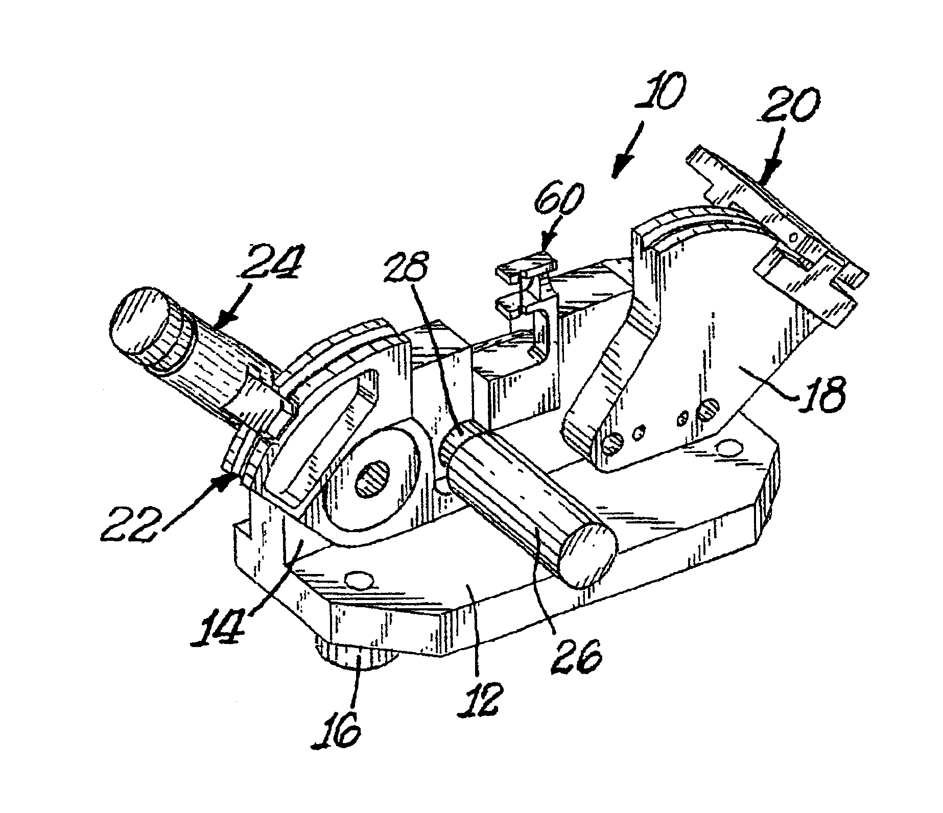
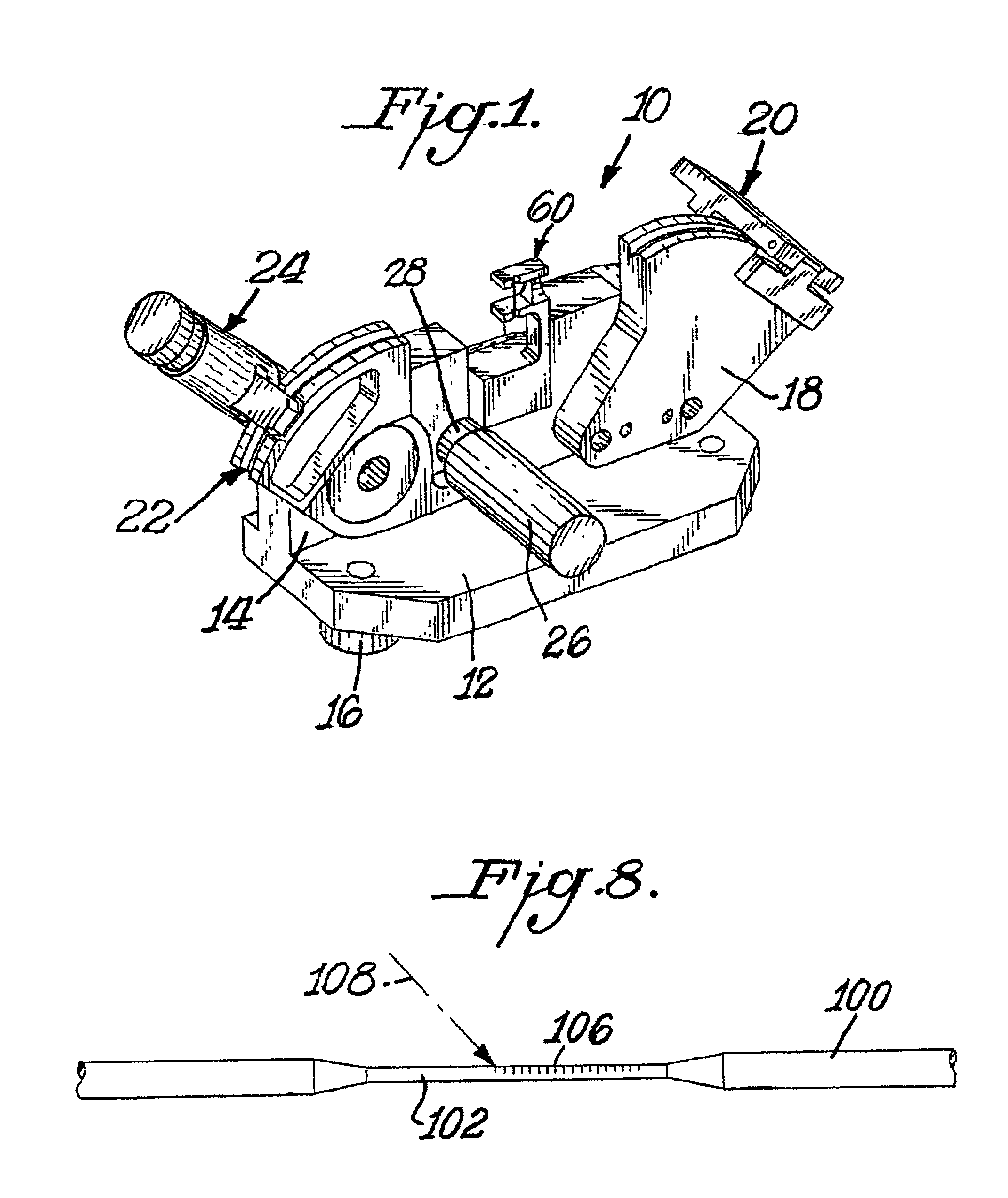
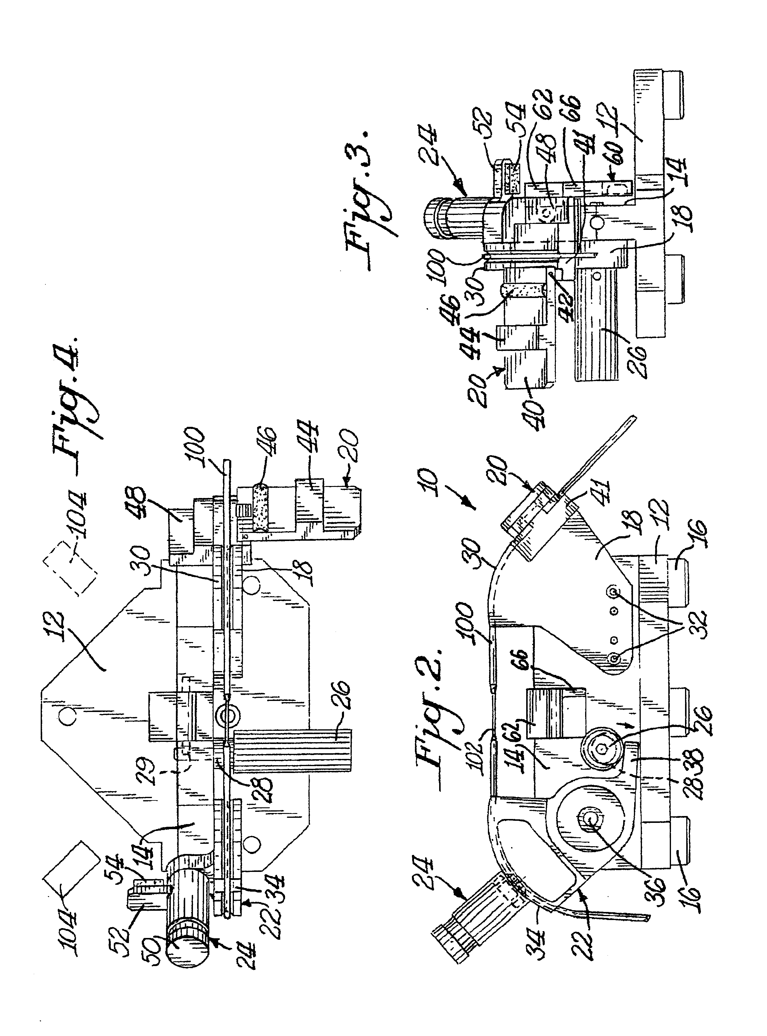
Referring now specifically to the drawings, a fiber optic cable tensioning and positioning apparatus according to the present invention is illustrated in FIG. 1, and shown generally as reference numeral 10. The tensioning apparatus 10 includes a horizontal base 12 integrally connected to a vertical support wall 14. A plurality of feet 16 supports base 12. A first fiber optic cable support 18 is rigidly affixed to a portion of vertical support wall 14. A first fiber optic cable clamp 20 connects to a portion of first fiber optic cable support 18.

A second fiber optic cable support 22 pivotally attaches to a portion of vertical support wall 14 and is spaced from first fiber optic cable support 18. A s...


PUM


Abstract

A method for tensioning and positioning a fiber optic cable includes providing and securing a first portion of the fiber optic cable in a first support with a first clamp. A second portion of the fiber optic cable is then provided in a second support, and secured thereto with a second clamp. A cam contacting the second support is then rotated, thereby rotating the second support due to its weight and the weight of the second clamp. The rotation of the second support creates a gravity-assisted moment arm that uniformly and repeatably tensions and positions the fiber optic cable. After the fiber optic cable is uniformly tensioned and positioned, a refractive-index grating may be etched in the glass optical fiber portion of the cable. Once the grating is etched, the cable may be removed by reversing the method.

Description

A. Field of the InventionThe present invention relates generally to the communications field, and, more particularly to a fiber optic cable tensioning and positioning apparatus and method for tensioning and positioning a fiber optic cable using the same.B. Description of the Related ArtAlong with the increasing prominence of the Internet has come the wide-ranging demand for increased communications capabilities, including more channels and greater bandwidth per channel. Optical media, such as fiber optic cables, promise an economical alternative to electrical conductors for high-bandwidth long-distance communications. A typical fiber optic cable includes a silica core (glass optical fiber), a silica cladding, and a protective coating. The glass optical fibers of fiber optic cables have very small diameters, which are susceptible to external influences such as mechanical stress and environmental conditions. The index of refraction of the core is higher than the index of refraction of...

Claims


Application Information

Patent Timeline
Patent Type & Authority Patents(United States)
IPC IPC(8): G02B6/02
CPCG02B6/02123G02B6/02133G02B6/02147G02B6/02152
Inventor MITCHELL, DAVID C.CUNNINGHAM, NOLAN SCOTTBOYER, THOMAS R.
Owner CIENA
Why Eureka
Try Eureka