Eureka AIR delivers breakthrough ideas for toughest innovation challenges, trusted by R&D personnel around the world.

Medicament transferring device

a transfer device and a technology for transferring devices, applied in the direction of pharmaceutical containers, packaging goods, packaged goods, etc., can solve the problems of reducing the amount of parts to be produced for the device, uncorrecting the larger dosage of the syringe, and shortening the transmission chain from the dosing means to the piston

Inactive Publication Date: 2004-06-29
NOVO NORDISK AS
View PDF14 Cites 18 Cited by
  • Summary
  • Abstract
  • Description
  • Claims
  • Application Information

AI Technical Summary

Benefits of technology

The piston is moved or forced forwards by the piston driver, which is activiated by the dosing means. The dosing means may be connected to the piston driver by means of a welding process, a gluing process, or a moulding process. In a preferred embodiment the dosing means is moulded unitarily with the piston driver. This reduces the amounts of parts to be produced for the device, and furthermore, the transmission chain from the dosing means to the piston is shortened which diminishes the variations in the dosing quantities.
In the present context, the movement towards the sealing is denoted forwards movement. The movement is calibrated, which in a preferred embodiment is made by providing the device with means for precisely indicating the volume of medicament which has been transferred from the vial to the syringe. The amount of medicament delivered into the syringe may be indicated in several ways. The amount can be easily and precisely controlled by controlling the number of full and partial revolutions of the dosing means relative to the vial. The control is eased by providing an audible sound for each partial revolution, e.g. a click per unit of medicament.
In another preferred embodiment the locking means are provided by arranging detent locks on the inner face of the dosing means corresponding to the threaded coupling on the container. Thereby, the coupling is functionally a unidirectionaly threaded coupling. In yet another embodiment the locking means are provided in the piston, such as metallic spring(s) inhibiting backward movement of the piston and thereby the piston driver.
In a preferred embodiment the needle is integrated in the syringe. Thereby the excess space in the needle and coupling between the needle and the syringe is diminished. This will lead to a more precise dosing in that only a small amount of air inherently present in the syringe / needle will interfere with dosage during injection.
The syringe may be mounted to the device by means of a syringe holder, such as a housing having a central bore, wherein the syringe is mounted pointing the needle towards the sealing of the container. The syringe holder may be coupled to the container via any suitable coupling means, such as a snap lock, a threaded coupling, a bajonet lock, a luer lock or a suitable combination thereof. The syringe holder may be releasably coupled to the container, whereby the syringe holder can be reused after emptying the container. In another embodiment, the syringe holder may be unitarily moulded with the container to reduce the amount of parts to be assembled after the moulding process.

Problems solved by technology

In practice it has proved a problem to design a material for a piston which is of sufficient strength to act as the piston while also being enough flexible to be pierced several times without leaking.
However, this kind of system exhibits another problem, namely that the piston may be drawn from the piston driver, if the person using the system, draw the syringe plunger rod before releasing the syringe from the syringe holder.
This will lead to an uncorrect larger dosage in the syringe.
This reduces the amounts of parts to be produced for the device, and furthermore, the transmission chain from the dosing means to the piston is shortened which diminishes the variations in the dosing quantities.

Method used


Image

  • Medicament transferring device
  • Medicament transferring device
  • Medicament transferring device

Examples


Embodiment Construction

In the following the invention is described in greater detail referring to the figures.

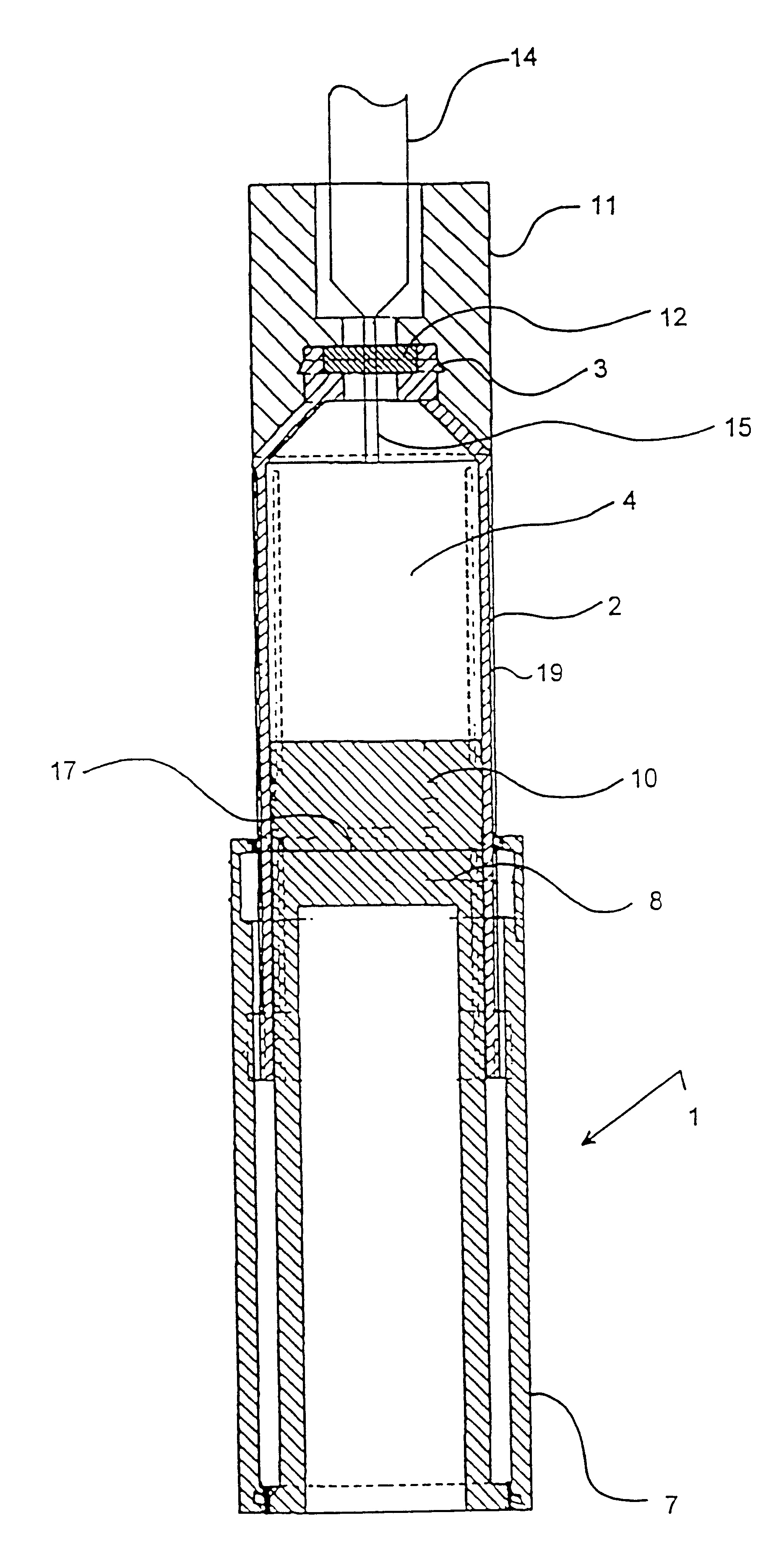
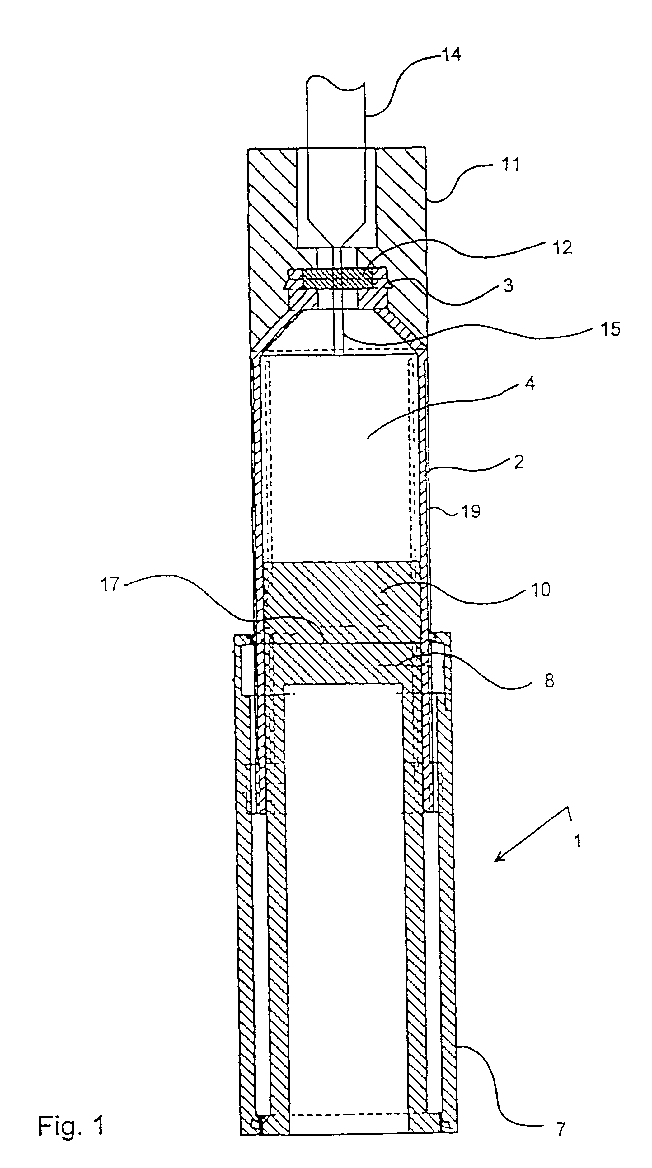
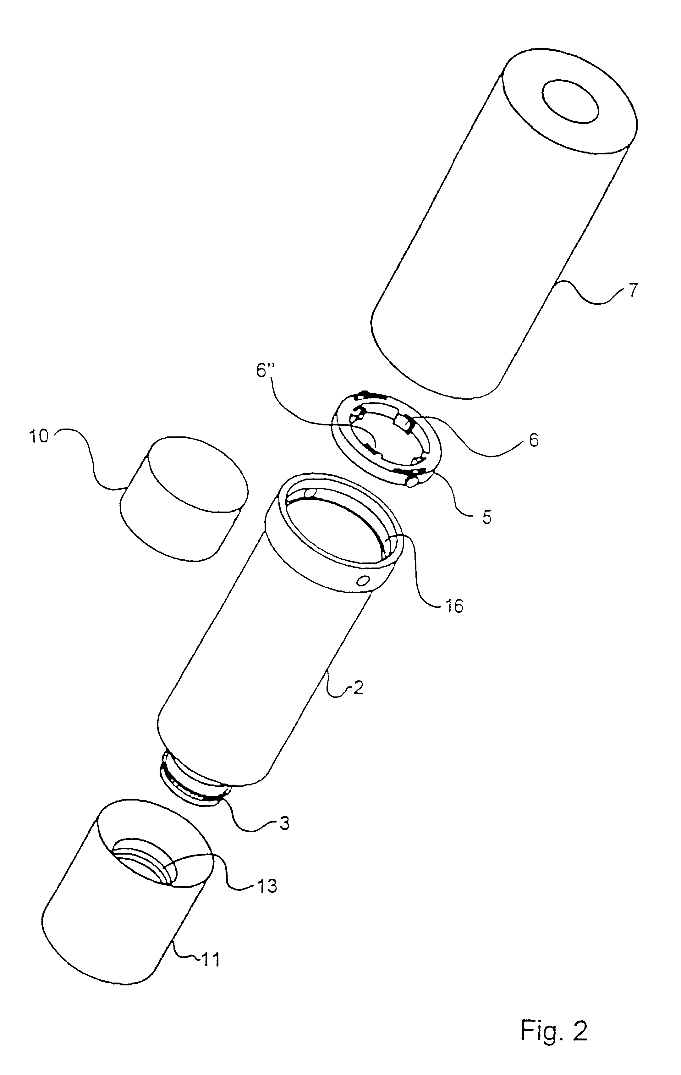
FIG. 1 shows the device 1 with the container 2 comprising one end with coupling means 3 for the syringe holder 11, said end being sealed with a sealing 12. The interior lumen 4 of the container is containing the medicament. FIG. 1 further shows the dosing means 7 mounted to the container 2 via a threaded coupling. Furthermore, container 2 comprises piston 10 moulded to by two-component process to the piston driver 8, the coupling between the piston and the piston driver is denoted 17. The piston is in slidable fluid-tight engagement with the container wall 19. The piston may be produced from any suitable material, such a rubber or a flexible plastic material.

In the syringe holder 1 the syringe 14 is mounted with the needle 15 piercing the sealing 12. In this position the device 1 is ready for dosing the correct amount of medicament from the container 2 to the syringe 14, by rotating the dosing mea...


PUM


Abstract

The present invention relates to a transfer device for transferring medicament from a medicament container to a syringe with a needle. The transfer device is arranged for transferring accurate dosages of insulin, growth hormone or other medicaments. The accuracy is ensured by the device comprising means for mounting a syringe to the device, the needle piercing a sealing of the device. Opposite the sealing a piston is arranged, said piston being non-releasable engaged with the piston driver during transfer of the medicament. Thereby the piston is not erroneously drawn from the piston driver, which would otherwise lead to incorrect dosing. Furthermore, the device comprises dosing means including the piston driver.

Description

The present invention relates to a transfer device for transferring medicaments to a syringe with needle as well as a method for filling syringes.PRIOR ARTSome patients may parentally administer medicaments on a regular basis. Medicaments, such as insulin or growth hormone, are very important to dose accurately. Often the dose is aspirated from a vial to a calibrated syringe, and due to the potency of the medicament it is important that the amount of the medicament aspirated into the syringe for each dose is precise. The accuracy depends on a variety of factors, such as the calibration of the syringe, the patient's vision as well as general motoric abilities to precisely dose the medicament.To encrease the accuracy several dosage measuring devices have been presented wherein the calibration is carried out by an apparatus whereby the medicament is expelled into the syringe from a vial. In some systems a syringe is coupled to a vial or container and the needle cannula on the syringe i...

Claims


Application Information

Patent Timeline
Patent Type & Authority Patents(United States)
IPC IPC(8): A61J1/00A61M5/178A61J1/20A61M5/315
CPCA61J1/2096A61M5/1782A61J2001/201A61M5/31511A61J1/201
Inventor BUCH-RASMUSSEN, THOMASPOULSEN, JENS-ULRIKLJUNGGREEN, HENRIK
Owner NOVO NORDISK AS
Why Eureka
Eureka Blog
Learn More