Charge pump based voltage regulator with smart power regulation

a voltage regulator and charging pump technology, applied in the field of voltage regulators, can solve the problems of limiting the speed of operation of a thyristor-based sram, wasting time, and wasting resources,

Inactive Publication Date: 2004-06-29
MICRON TECH INC +1
View PDF14 Cites 57 Cited by
  • Summary
  • Abstract
  • Description
  • Claims
  • Application Information

AI Technical Summary

Problems solved by technology

Switching between the on state and the off state of a thyristor however, takes rather a long time due to the long life time o

Method used


Image

  • Charge pump based voltage regulator with smart power regulation
  • Charge pump based voltage regulator with smart power regulation
  • Charge pump based voltage regulator with smart power regulation

Examples


Embodiment Construction

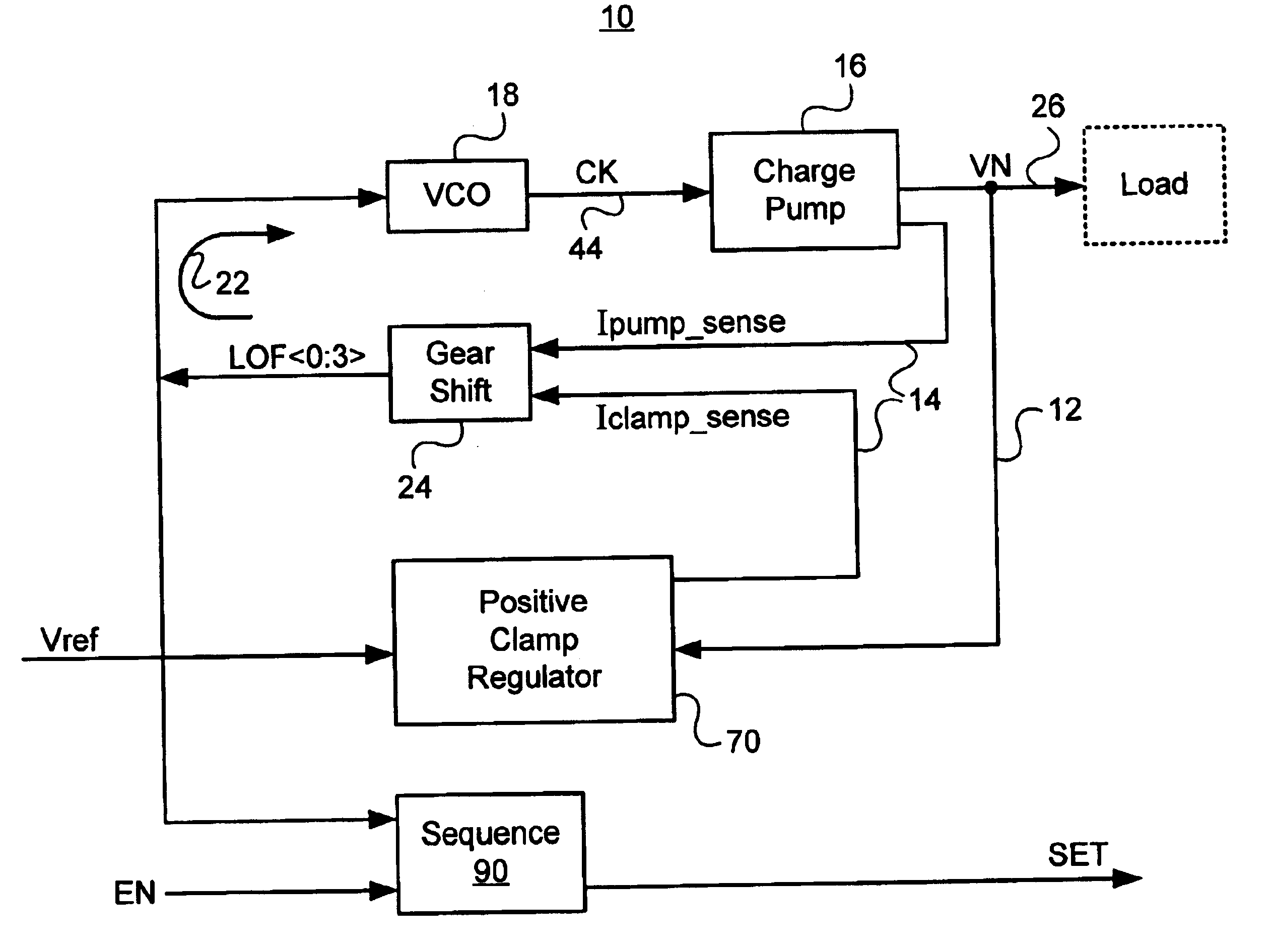
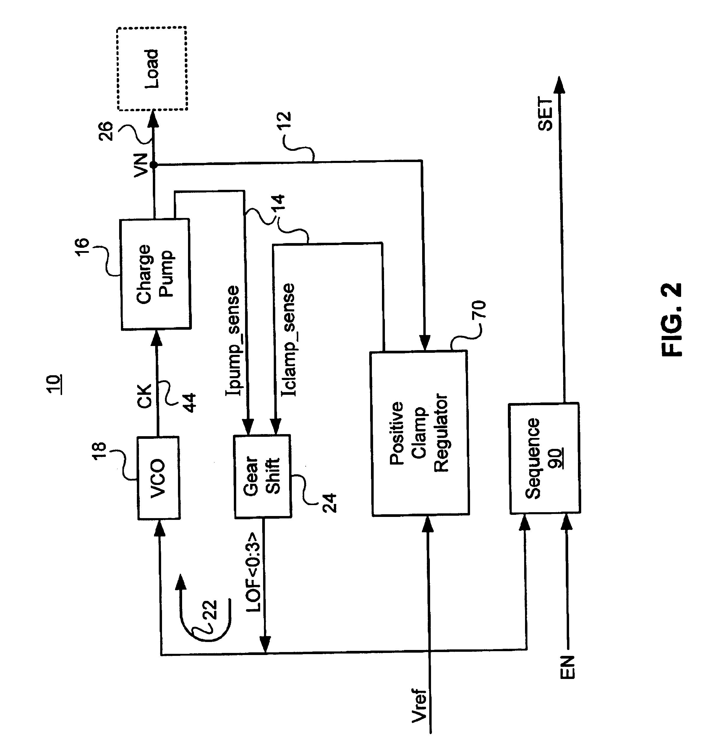
Charge pumps (CPs) are commonly used inside an IC to generate either a negative voltage or a positive voltage larger than the external supply voltage powering-up the IC. CPs of various types (NMOSFET or PMOSFET-based, with or without bootstrapping) have been developed since the early days of silicon-based MOS technologies. They were also implemented in bipolar technologies. CPs are notorious for three undesirable deficiencies. First and foremost they are very inefficient in terms of circuit area and overall power dissipation. They require a large amount of capacitor which occupies a large area on an IC (relatively to other circuit blocks and functions on the IC). Their inefficiency is further worsened by their sensitivity to leakage currents and the effect of circuit parasitic capacitances. CP power efficiency is very low, often less than 10% and seldom above 25%. The efficiency tends to decrease as the CP output current loading requirements and the magnitude of the output voltage a...


PUM


Abstract

A charge pump based voltage regulator with smart power regulation employs an architecture that requires that the charge pump current be a linear combination of the load current and a clamp current with a possible offset current. The smart power regulation is based on automatic load activity (or load current) detection using the clamp current. The clamp current and the filtered charge pump current are compared with one another; and the charge pump current is then adjusted accordingly by stepping the frequency of the clock driving the charge pump, optimizing the power consumption of the entire voltage regulator with varying load activity. The negative voltage regulation is independent of the integrated circuit positive supply voltage. In one embodiment, a derivative of the desired output voltage is compared with a reference voltage to generate a clamp current control signal. In another embodiment, the reference voltage is solely positive.

Description

1. Field of the InventionThis invention relates generally to voltage regulators, and more particularly to a charge pump based voltage regulator with smart power regulation.2. Description of the Prior ArtA conventional SRAM device employs SRAM cells, each cell consisting of four or six transistors. A thyristor based SRAM cell consists of only two devices, the thyristor itself, and a pass transistor. An SRAM device comprising thyristor SRAM cells will thus be much more compact and much less costly.Switching between the on state and the off state of a thyristor however, takes rather a long time due to the long life time of the minority carriers in the P-base. This characteristic undesirably limits the speed of operation of a thyristor-based SRAM. A thinly capacitively coupled thyristor (TCCT) to significantly speed up the switching has been disclosed in U.S. Pat. No. 6,229,161, entitled Semiconductor capacitively-coupled NDR Device And Its Applications In High-Density High-Speed Memori...

Claims


Application Information

Patent Timeline
IPC IPC(8): H02M3/07H02M3/04G11C5/14G11C11/412
CPCG11C5/14G11C5/145G11C11/412H02M3/073H02M2001/0009H02M2003/071H02M1/0009H02M3/071
Inventor WU, DANDANDERMY, PLERRE
Owner MICRON TECH INC
Why Eureka
Try Eureka