Method for forming throughhole in ink-jet print head

a technology of inkjet printing and throughholes, which is applied in the field of fabricating throughholes in inkjet printing heads, can solve the problems of cracks or damage to throughhole openings formed by such a technique, and the technique is not suitable for mass production of inkjet printing heads

Inactive Publication Date: 2004-07-06
SAMSUNG ELECTRONICS CO LTD
View PDF8 Cites 25 Cited by
  • Summary
  • Abstract
  • Description
  • Claims
  • Application Information

AI Technical Summary

Benefits of technology

To solve the above problems, it is a first object of the present invention to provide a method for forming a throughhole in an ink-jet print he

Problems solved by technology

However, such a technique has several significant disadvantages.
Specifically, such a technique is not suitable for mass production of the ink-j

Method used


Image

  • Method for forming throughhole in ink-jet print head
  • Method for forming throughhole in ink-jet print head
  • Method for forming throughhole in ink-jet print head

Examples


Embodiment Construction

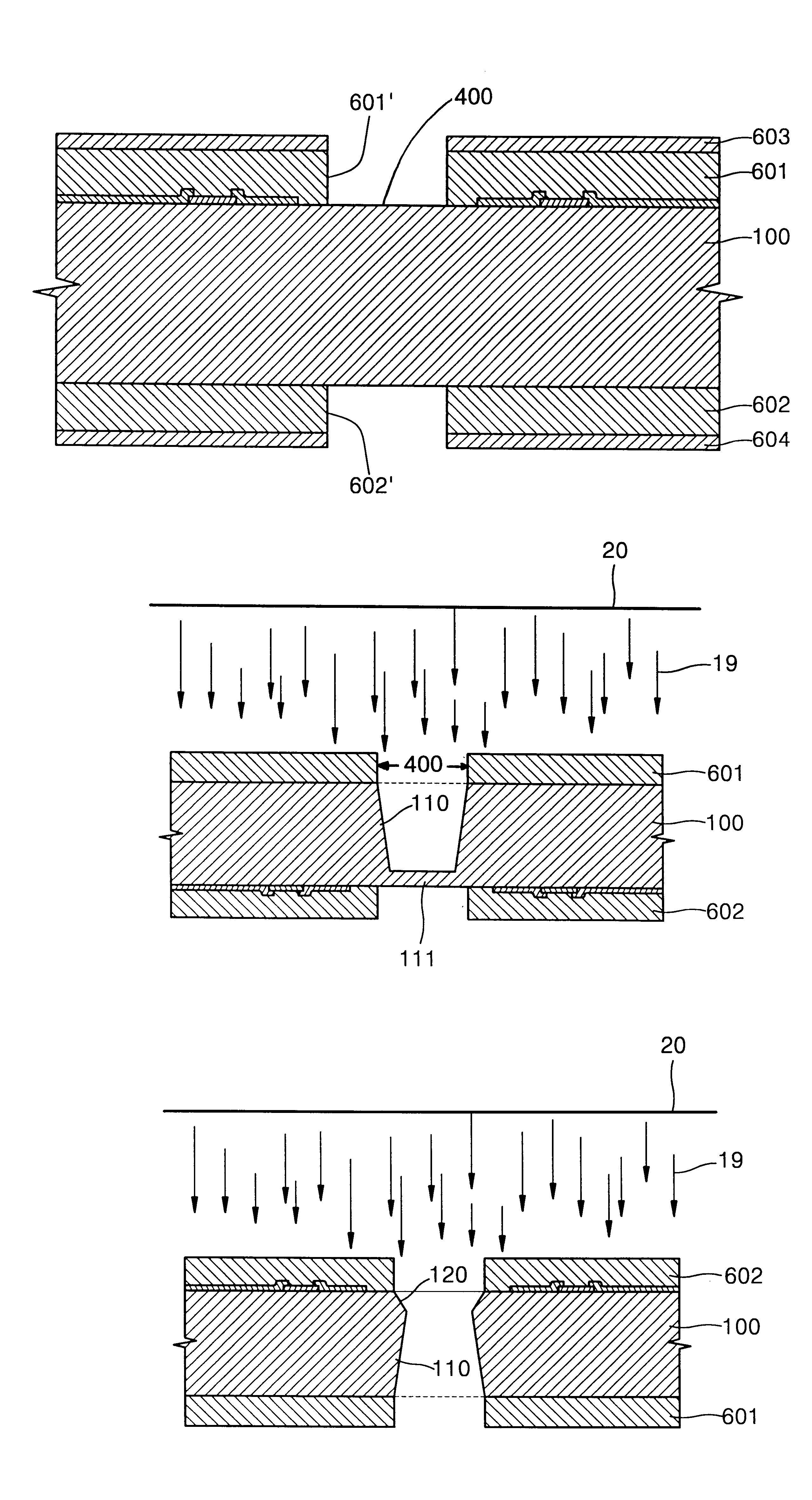
A process for forming a bubble-generator before forming a throughhole will be excluded in the following description. The process for forming a bubble-generator is performed by well-known processes. The bubble-generator includes a heater, a signal line connected to the heater, an electrode pad provided on an end portion of the signal line, and an insulating layer for protecting the elements and preventing contact with ink. That is, the ink-jet print head according to the present invention has the structure shown in FIG. 1, but the form of the throughhole formed by the present invention is slightly different from that of the print head shown in FIG. 1.

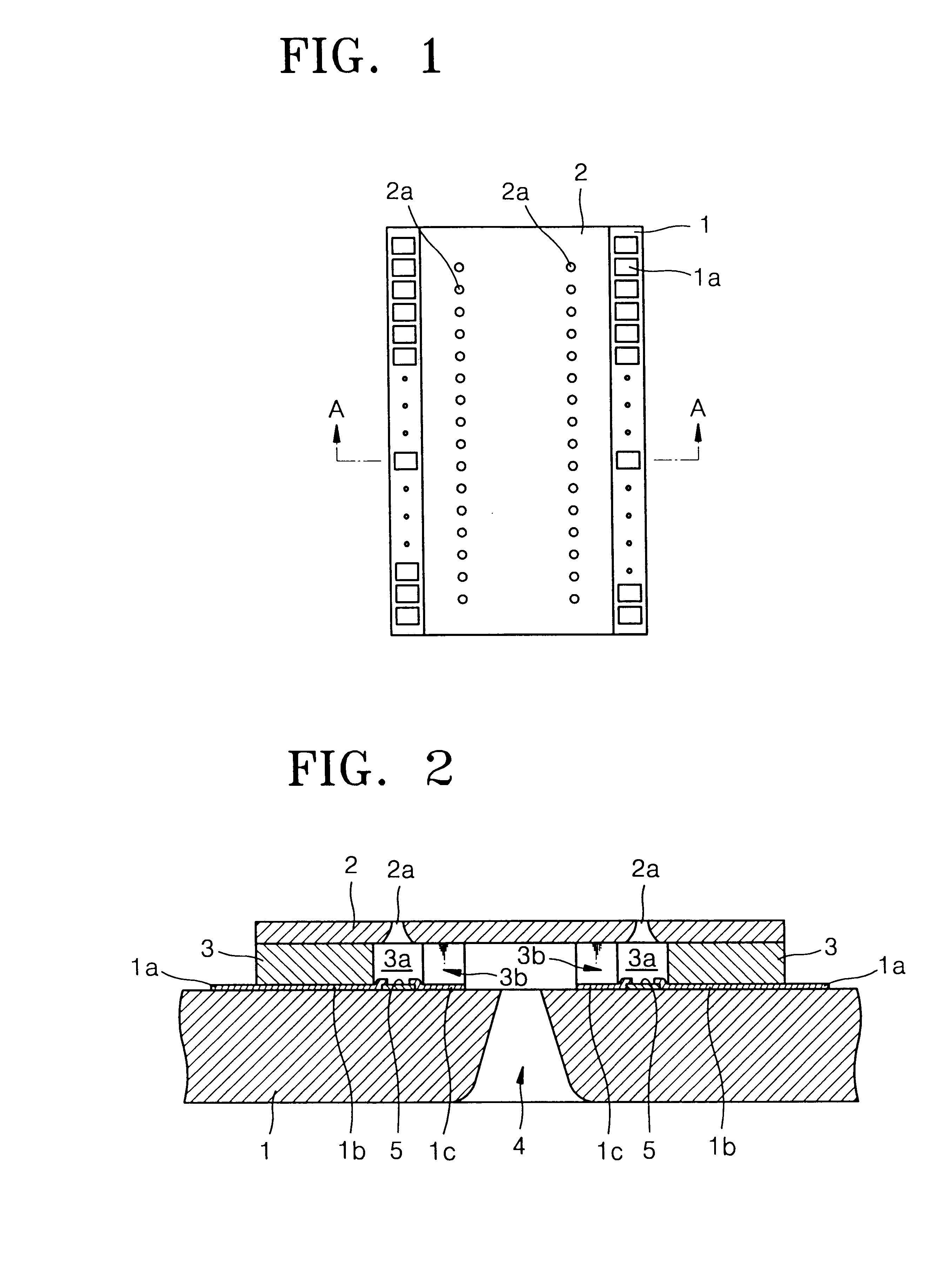
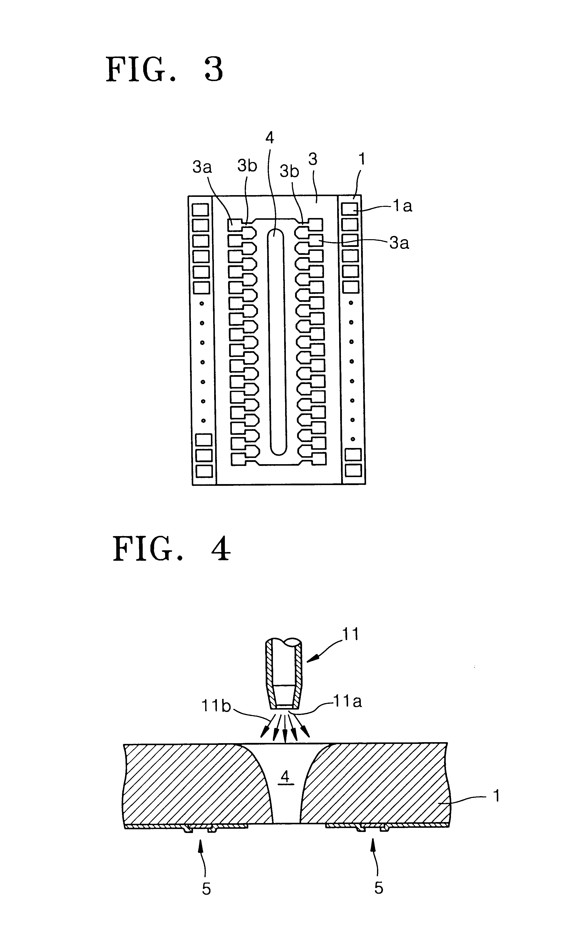
FIG. 1 is a plan view of an ink-jet print head, FIG. 2 is a sectional view taken along line A--A of FIG. 1, and FIG. 3 is a plan view of the structure of an ink chamber in a state where a nozzle plate is removed from the ink-jet print head shown in FIG. 1.

Referring to FIGS. 1 thru 3, electrode pads 1a are arranged at a predetermined inte...


PUM

PropertyMeasurementUnit
Pressureaaaaaaaaaa
Sizeaaaaaaaaaa
Speedaaaaaaaaaa

Abstract

A method for forming a throughhole in an ink-jet print head of a bubble-jet system includes the steps of: forming a bubble-generator which is adjacent to a throughhole-forming region on one side of a substrate, and which includes a heater; forming a first mask layer for covering portions excluding the throughhole-forming region on a first side of the substrate; forming a second mask layer for covering portions excluding the throughhole-forming region on a second side of the substrate; forming a first well with a predetermined depth on the throughhole-forming region of the substrate not covered by the first mask layer by spraying sand under high pressure and at a high speed onto the first side of the substrate; forming a second well corresponding to the first well on the throughhole-forming region of the substrate not covered by the second mask layer by spraying sand under high pressure and at a high speed onto the second side of the substrate; forming a throughhole by overlap of the first well and the second well on the throughhole-forming region; and removing the first and second mask layers. Accordingly, a plurality of throughholes can be formed on a plurality of substrates at one time, and the time required for processing throughholes on one wafer can be reduced considerably compared to prior techniques, thereby promoting mass production. Furthermore, the size of the nozzle for spraying the sand, and consequently the size of the throughhole, is uniform and does not change. The size of the throughhole is determined by the mask layers, thereby forming a throughhole having a very uniform size with high precision.

Description

CLAIM OF PRIORITYThis application makes reference to, incorporates the same herein, and claims all benefits accruing under 35 U.S.C. .sctn.119 from my application FORMING METHOD OF VIA-HOLE IN INK-JET PRINT HEAD filed with the Korean Industrial Property Office on Jul. 27, 2000 and there duly assigned Ser. No. 43339 / 2000.BACKGROUND OF THE INVENTION1. Technical FieldThe present invention relates to a method for fabricating an ink-jet print head and, more particularly, to a method for forming a throughhole in an ink-jet print head.2. Related ArtMethods for discharging ink in an ink-jet printer include use of an electro-thermal transducer (the so-called "bubble-jet method") for generating bubbles in ink and discharging the ink using a heat source. The electromechanical transducer discharges ink by varying the ink volume using piezoelectricity.Such methods involve the use of an ink-jet print head having a throughhole formed in a substrate thereof for supplying ink through ink channels to...

Claims


Application Information

Patent Timeline
IPC IPC(8): B41J2/16B41J2/235B24C1/00B24C1/04B41J2/05
CPCB41J2/1603B41J2/1626B41J2/1631B41J2/1635B41J2/1645B41J2/1632Y10T29/49401B41J2/235
Inventor PARK, LAE-SOO
Owner SAMSUNG ELECTRONICS CO LTD
Why Eureka
Try Eureka