Turbomachine injectors

a technology of injectors and turbomachines, which is applied in the direction of process and machine control, instruments, lighting and heating apparatus, etc., can solve the problems of non-uniformity between injectors, unsatisfactory operation of turbomachine engines, and unsatisfactory flow rates from one injector, so as to reduce non-uniformity between injectors and achieve the effect of reducing such drawbacks, reducing the number of injections, and reducing the number of injection

Inactive Publication Date: 2004-07-06
HISPANO SUIZA SA
View PDF14 Cites 6 Cited by
  • Summary
  • Abstract
  • Description
  • Claims
  • Application Information

AI Technical Summary

Benefits of technology

The present invention thus seeks to mitigate such drawbacks by proposing a fuel injector which enables non-uniformity between injectors to be decreased. Another object of the invention is to propose an injector that is simpler to make and to improve the adjustment performance at medium rates of fuel flow.
The rate at which fuel is admitted into the injector body is a function in particular of the diaphragm. It is fixed at a determined value by selecting a diaphragm opening as a function of technical characteristics that are specific to each injector in the same combustion chamber. More precisely, the diaphragm selected for each injector is chosen as a function of the departure of its flow rate from a design medium flow rate. Thus, each injector in a given combustion chamber is provided with a diaphragm which may differ from one injector to another. As a result, any risk of the various injectors delivering different flow rates is eliminated. In addition, it is easy to replace a diaphragm since it does not require both valves to be disassembled.

Problems solved by technology

In practice, it is found that in a combustion chamber fed with fuel via a plurality of injectors of the kind described above, when the injectors are all subjected to the same feed pressure corresponding to medium flow rates, they deliver flow rates that are not uniform from one injector to another.
This non-uniformity is due mainly to manufacturing dispersions between their respective metering valves, and it can be as great as 10%.
At medium rates of flow this gives rise to non-uniformity between injectors which is harmful for proper operations of the turbomachine engine.

Method used


Image

  • Turbomachine injectors
  • Turbomachine injectors
  • Turbomachine injectors

Examples


Embodiment Construction

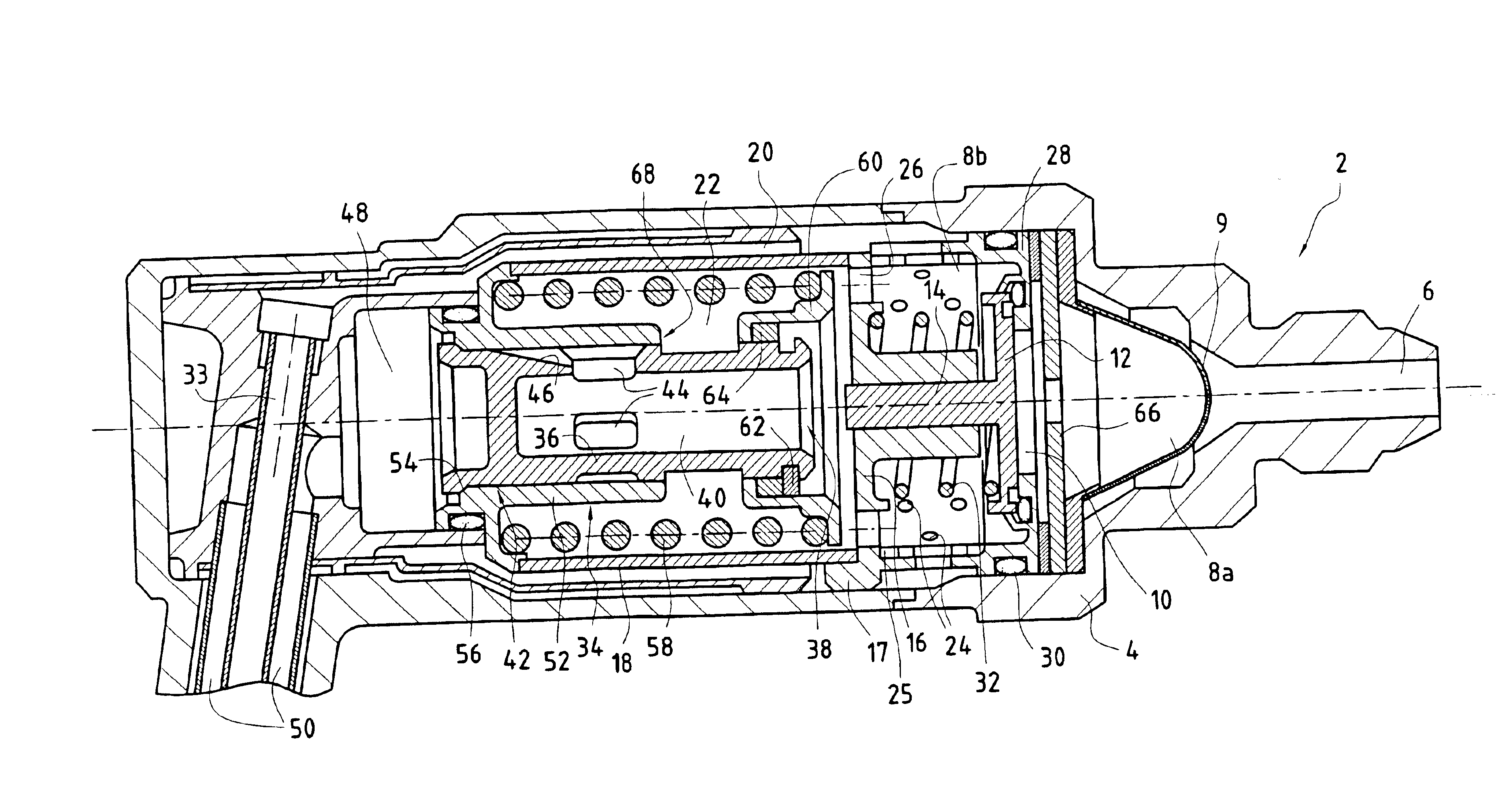
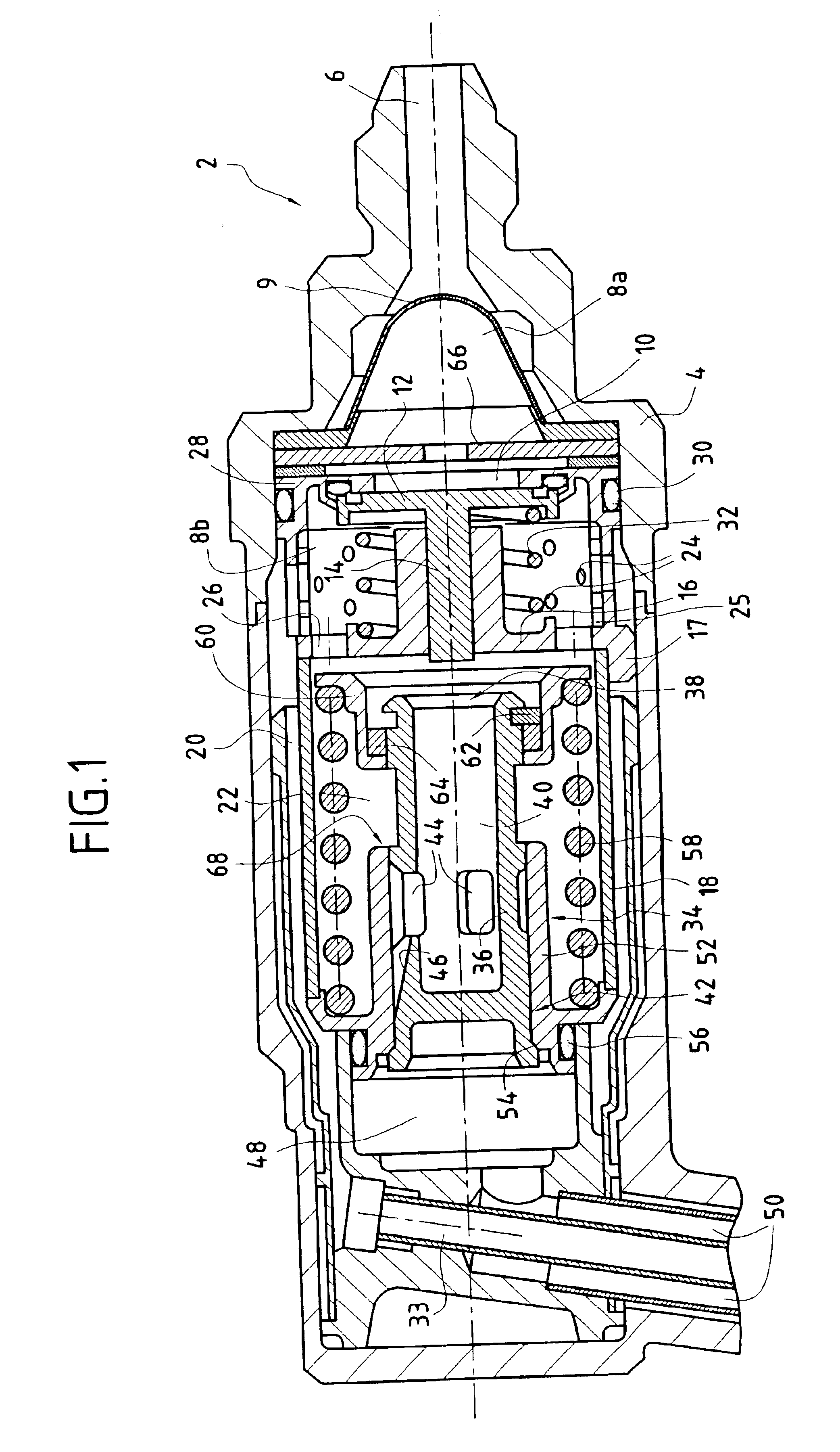
Reference is made to FIG. 1 which is a longitudinal section through a fuel injector of the invention for a turbomachine engine.

This injector is of the aeromechanical type, i.e. it is designed to deliver two fuel flows: a primary flow during a stage of starting the turbomachine fitted with this injector and a stage of operating at low power; and a secondary flow for subsequent stages of operation up to full power.

In the invention, the fuel injector 2 comprises an injector body 4 containing a fuel admission orifice 6 for receiving fuel under pressure from a suitable pump (not shown) and opening out into a pre-admission chamber 8a after passing through strainer type filter means 9. A sealing valve 10 for sealing of the injector when not in operation is mounted in an admission chamber 8b disposed downstream from the pre-admission chamber 8a in the fuel flow direction. It is conventionally formed by a valve head 12 and a valve stem 14 and it is held in position by means of a tubular cent...


PUM


Abstract

A fuel injector for a turbomachine engine, the injector comprising an injector body having pressurized fuel admission means, a first valve mounted downstream from the pressurized fuel admission means and arranged to admit fuel into the injector body, a second valve mounted downstream from the first valve and capable of opening in order to meter at least a fraction of the fuel admitted into the injector body for utilization means for using the fuel, the metered fuel flow rate to the utilization means being a function of flow sections formed through the second valve, the injector further comprising a diaphragm placed between the pressurized fuel admission means and the first valve so as to set the rate at which fuel is admitted into the injector body at a determined value.

Description

The present invention relates to improvements applied to fuel injectors for a turbomachine engine. More particularly the invention relates to adjusting the rate at which fuel is injected into a turbomachine combustion chamber.In conventional manner, a turbomachine engine comprises a plurality of injectors enabling the combustion chamber to be fed with fuel and air during starting and normal operation of the turbomachine engine. There exists two main types of injector: "aeromechanical" injectors designed for two fuel flow rates (a primary rate and a secondary rate) depending on the operating stage of the engine (lighting, from low to full power), and "aerodynamic" injectors which have a single fuel circuit for all operating stages. The present invention relates more particularly to injectors of the first category.In conventional manner, an aeromechanical fuel injector for a turbomachine engine comprises two fuel feed circuits: a primary circuit corresponding to low feed rates (for us...

Claims


Application Information

Patent Timeline
Patent Type & Authority Patents(United States)
IPC IPC(8): F23K5/02F23K5/14
CPCF23K5/147Y10T137/2663
Inventor MICHAU, MARIONRODRIGUES, JOSETIEPEL, ALAIN
Owner HISPANO SUIZA SA
Why Eureka
Try Eureka