Method of improving retard mechanism in friction feeders

a technology of friction feeder and retard mechanism, which is applied in the direction of thin material processing, article separation, transportation and packaging, etc., can solve the problems of reducing the effectiveness of the retarding surface 50, sporadic and inconvenient manual method of furnishing an unworn portion of the retarding surface, and reducing the roughness of the surface, so as to achieve simple yet effective

Inactive Publication Date: 2004-07-06
DMT SOLUTIONS GLOBAL CORP
View PDF9 Cites 8 Cited by
  • Summary
  • Abstract
  • Description
  • Claims
  • Application Information

AI Technical Summary

Benefits of technology

It is an objective of the present invention to provide a simple yet effective method and device to automatically furnish an unworn portion of the retarding surface in a friction feeder while the feeder is in operation. This objective can be achieved by using a cylindrical retarding member, which is allowed to rotate freely in one direction along its rotational axis but is prevented from rotating in the other direction. The retarding member is caused to rotate against the feeding direction of the friction feeder by a pre-determined amount after or before a sheet is driven out of the exit nip.
the driving mechanism is adapted to move in a retracting direction opposite to the driving direction in an intermittent manner so as to move at least one of the other flat items in a direction opposite to the exiting direction, thereby causing the cylindrical member to intermittently rotate in the first rotating direction by the second frictional force. The driving mechanism moves in the retracting direction prior to said one flat item being released or after said one flat item has exited the exit point.
The third aspect of the present invention is a method of improving a retarding action of a retarding mechanism in a feeder for releasing generally flat items from a stack, the feeder comprising a driving mechanism capable of moving in a driving direction in order to release one flat item at a time through an exit point, with the leading edge of said one flat item exiting the exit point in an exiting direction on a singulation plane, wherein the retard mechanism is positioned relative to the exit point to prevent other flat items in the stack adjacent to said one flat item from being drawn out of the exit point by a first frictional force between adjacent flat items while said one flat item is exiting the exit point, wherein the retard mechanism comprises:
moving the driving mechanism in a retracting driving direction opposite to the first driving direction in an intermittent manner so as to move at least one of the other flat items in a direction opposite to the exiting direction, thereby causing the cylindrical member to intermittently rotate in the first rotating direction by the second frictional force.
The fourth aspect of the present invention is a retard element to be engaged with a retard mechanism in a feeder for releasing generally flat items from a stack, the feeder having a driving mechanism capable of moving in a driving direction for releasing one flat item at a time through an exit point, with the leading edge of said one item exiting the exit point in an exiting direction on a singulation plane, wherein the retard mechanism is positioned relative to the exit point to prevent other flat items in the stack adjacent to said one flat item from being drawn out of the exit point by a first frictional force between adjacent flat items while said one flat item is exiting the exit point. The retard element comprises:

Problems solved by technology

After extensive use, the surface roughness is reduced mainly because of the accumulated paper dust, thereby reducing the effectiveness of the retarding surface 50.
This manual method of furnishing an unworn portion of the retarding surface is sporadic and inconvenient.

Method used


Image

  • Method of improving retard mechanism in friction feeders
  • Method of improving retard mechanism in friction feeders
  • Method of improving retard mechanism in friction feeders

Examples


Embodiment Construction

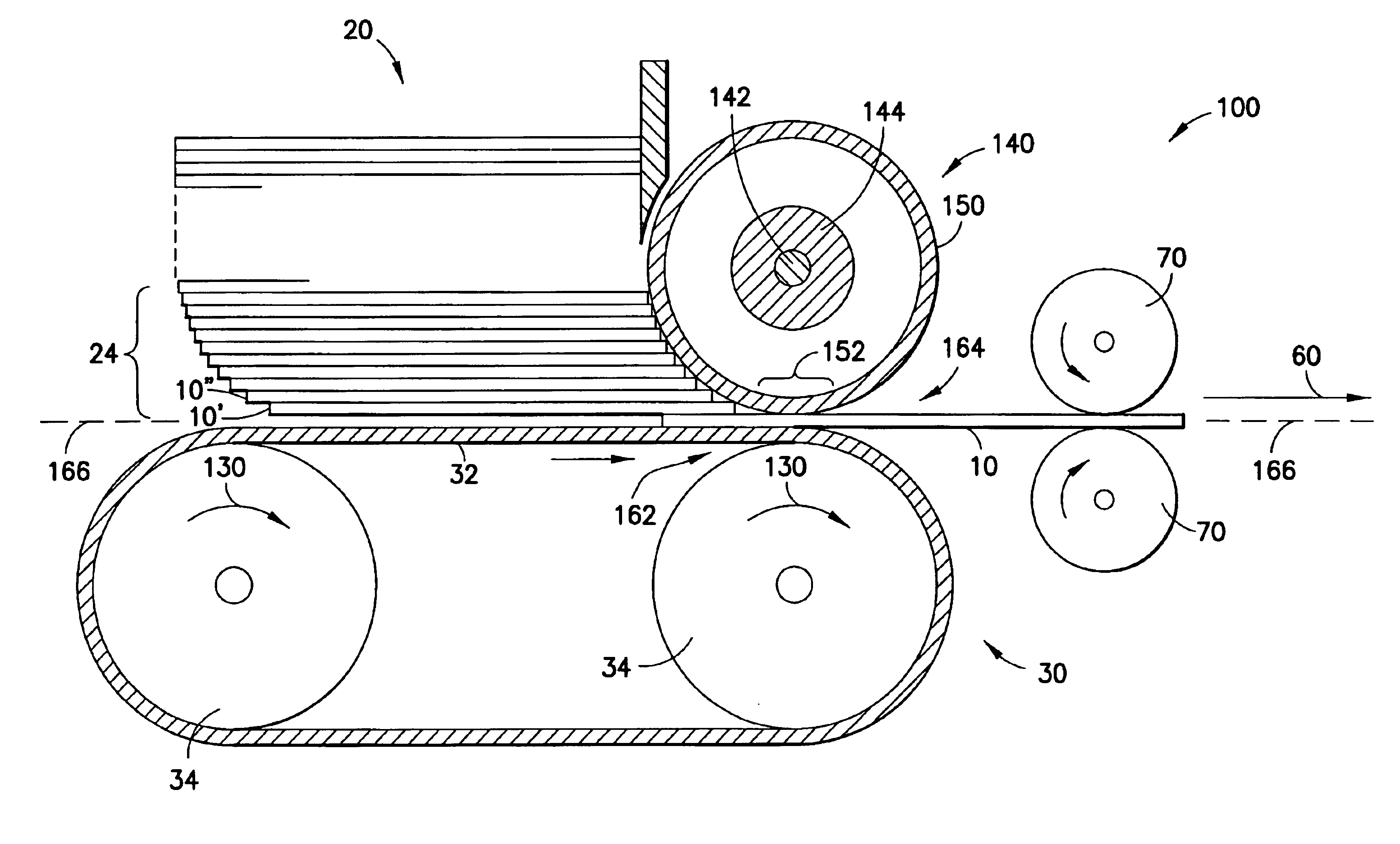
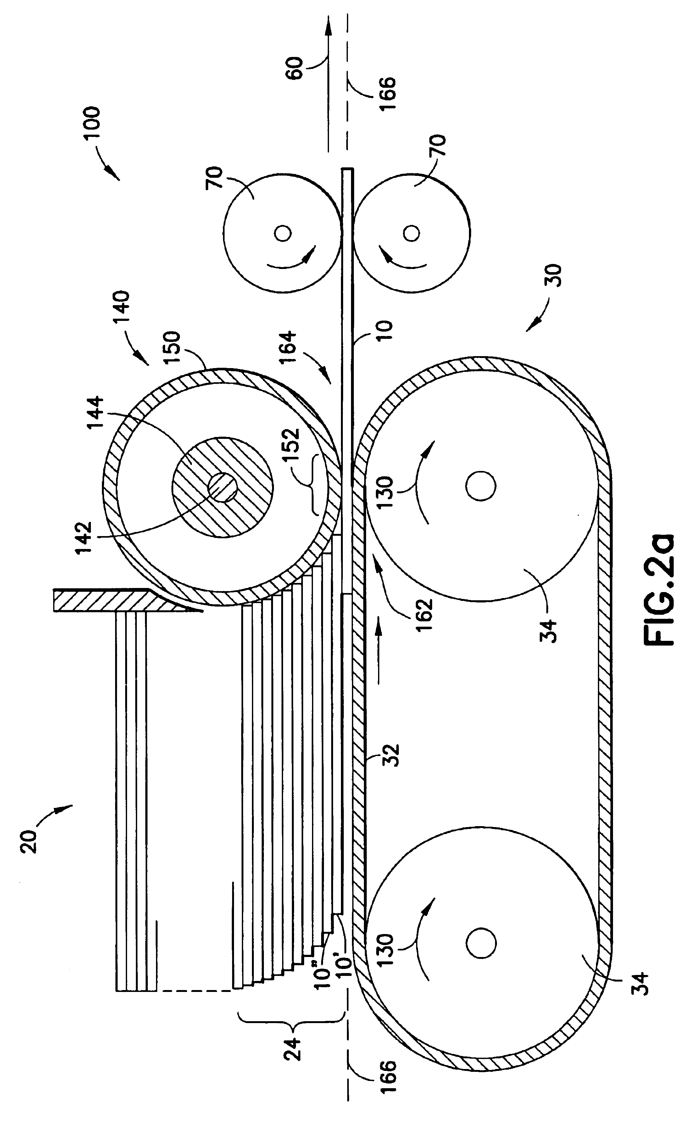
The present invention prevents the retarding surface from being worn out unevenly at one section thereof. Although the retarding surface will be eventually worn out after extensive use, the wear will be spread out over the entire circumference of the retarding surface in a simple and automatic fashion. As shown in FIG. 2a, the friction feeder 100, according to the present invention, comprises a generally cylindrical retarding element 140 having a retarding surface 150. The retarding surface 150 can be made of a hard material such as tungsten carbide grit, but it is preferred that it is made of a resilient material such as polyurethane or rubber. A resilient surface can be slightly deformed to allow for a reasonable gap between the retarding surface 150 and the driving mechanism 30 to form an the exit nip 164, even if the nip is set slightly fighter than normal. The retarding element 140 comprises a clutch mechanism 144 around the shaft 142 such that the retarding element 140 is lock...


PUM

PropertyMeasurementUnit
resilientaaaaaaaaaa
frictionaaaaaaaaaa
timeaaaaaaaaaa

Abstract

A sheet feeder having a driving mechanism to release sheets of document from a stack out of an exit nip, one sheet at a time. A retard mechanism is used to prevent other sheets from being drawn out of the exit nip by the frictional force between the sheets. The retard mechanism has a frictional surface driven by a cylinder, which is allowed to rotate freely in only one direction to move the frictional surface against the editing direction of the released sheet. The driving mechanism is programmed to move backward in an intermittent manner to move the sheets in the bottom of the stack away from the exit nip so as to cause the cylinder to rotate in order to spread out the wear of the frictional surface. Preferably, the frictional surface has a plurality of cuts in a helical or partially helical pattern.

Description

The present invention relates generally to a feeder for feeding mail related items such as mail insert materials, envelopes or mailpieces and, more specifically, to a retarding element in a friction feeder for preventing multiple feeds.Friction feeders are known in the art. As the name suggests, a friction feeder relies on the interaction of several components around the exit nip of the feeder that results in the singulation of paper documents in a paper stack. The common components in most friction feeders are the driving mechanism to drive a sheet of paper document out of the exit nip and the retarding element to retain all the other sheets in the stack so as to prevent multiple feeds. To provide the necessary friction for retaining the other sheets in the stack, the surface of the retarding element is usually made of an elastomeric material or a hard, rough coating. Ifkovits, Jr. et al. (U.S. Pat. No. 5,294,102, hereafter referred to as Ifkovits) discloses a friction feeder where...

Claims


Application Information

Patent Timeline
Patent Type & Authority Patents(United States)
IPC IPC(8): B65H3/04B65H3/02B65H3/52
CPCB65H3/042B65H3/5284B65H2301/42322B65H3/523
Inventor DACUNHA, STEVEN J.SKINGER, GREGORY P.DEPOL, ARTHUR H.NASH, THOMAS P.
Owner DMT SOLUTIONS GLOBAL CORP
Why Eureka
Try Eureka