Tip trailer

a trailer and tip technology, applied in the field of tip trailers, can solve the problems of affecting the design of conventional bins, affecting the safety of passengers, and limiting factors, and achieve the effect of preventing the twisting of the bin during tipping and simple and relatively inexpensive hydraulics

Inactive Publication Date: 2004-07-13
MATHEWS MARK
View PDF21 Cites 6 Cited by
  • Summary
  • Abstract
  • Description
  • Claims
  • Application Information

AI Technical Summary

Benefits of technology

The overhead beams of the fifth aspect of the invention also overcome or ameliorate a significant problem in prior art side tippers, which can undergo significant twist or torque when the bin is tipped. This twist is often due to an uneven load distribution in the bin or to an uneven lifting force provided by two or more hydraulic tipping rams. Complex proportioning of the forces exerted by the rams is often the only solution to this problem. The overhead beams of the present invention significantly strengthen and stiffen the bin, which enables simple and relatively inexpensive hydraulics to be used. In embodiments where such are provided, large transverse trusses also assist in stiffening the bin and preventing twist in the bin during tipping.

Problems solved by technology

Furthermore, in designing the bin of tip trailers, a number of limiting factors come into play.
However, conventional bin designs are hampered in this regard by the need for elements between the wheels and the floor of the bin.
In particular, the turnplate must be sufficiently strong to withstand the forces created between the prime mover and the trailer during use, for example by acceleration and cornering, and therefore is typically quite bulky.
However, reducing the dimensions of the bin limits the volume of the bin.
However, where the material to be carried is not dense, the limited volume of the bin often results in a full load weighing significantly less than the legal weight limit, and so a larger number of loads are required, increasing the time and cost of transporting the material.
A further limitation placed on the design of tip trailers results from the conflicting requirements of (a) robustness and strength in the bin and (b) reducing the weight of the bin as much as possible.
However, this increases fuel consumption and, due to the legal weight limit, reduces the weight of a load which may be carried.

Method used


Image

  • Tip trailer
  • Tip trailer
  • Tip trailer

Examples


Embodiment Construction

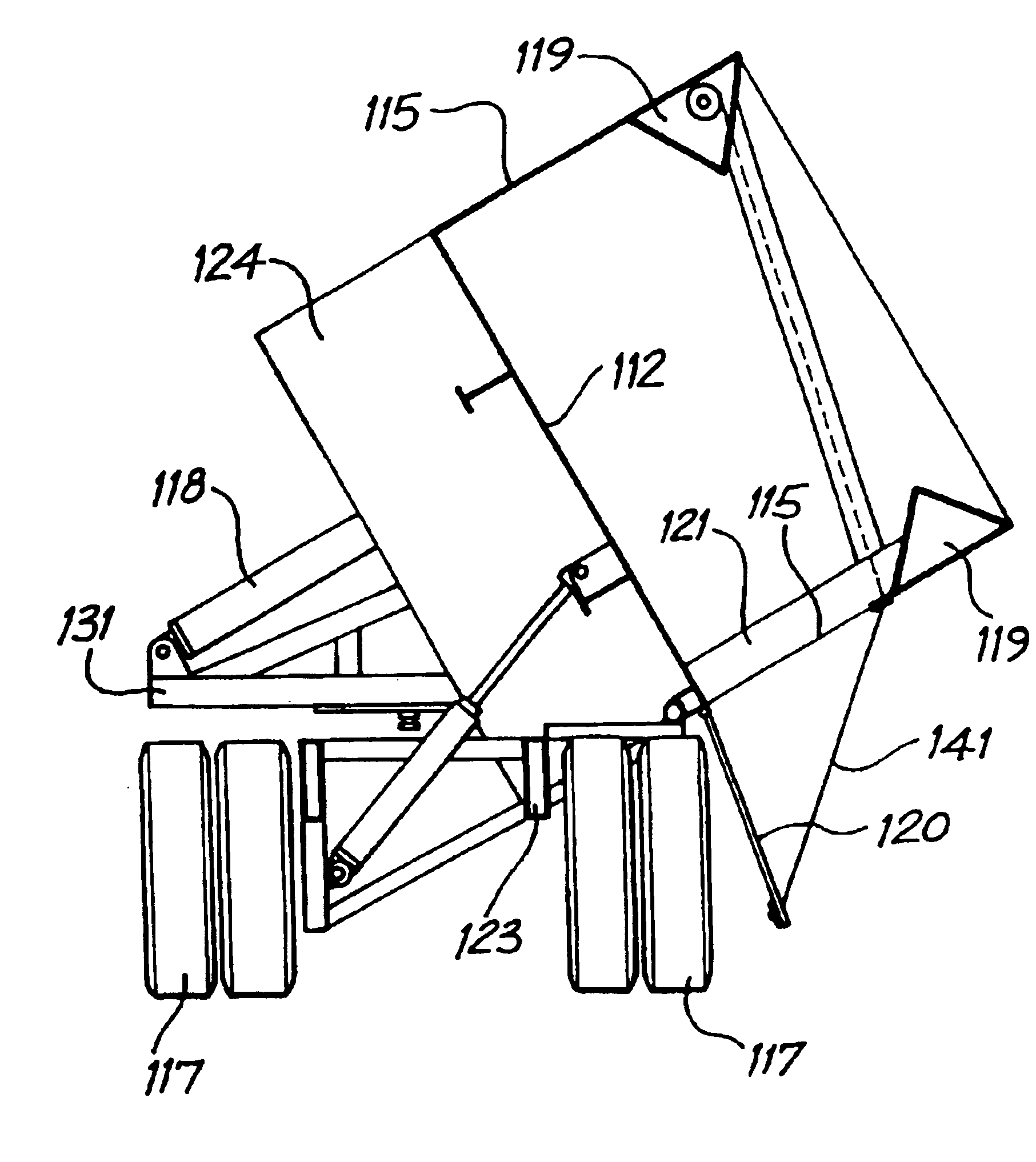
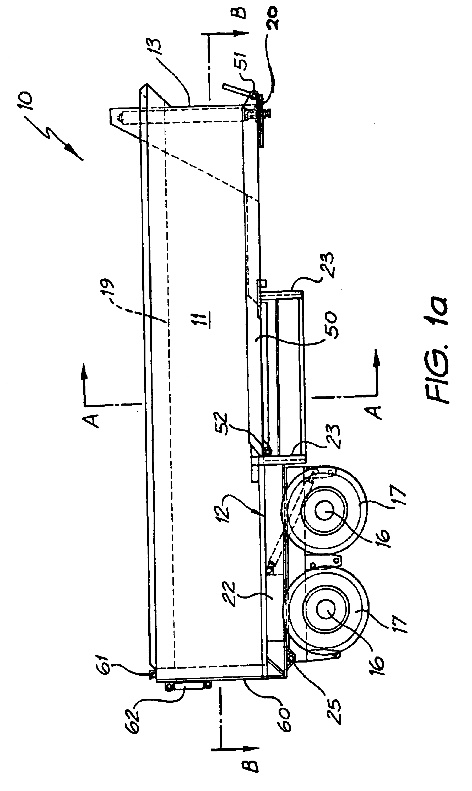
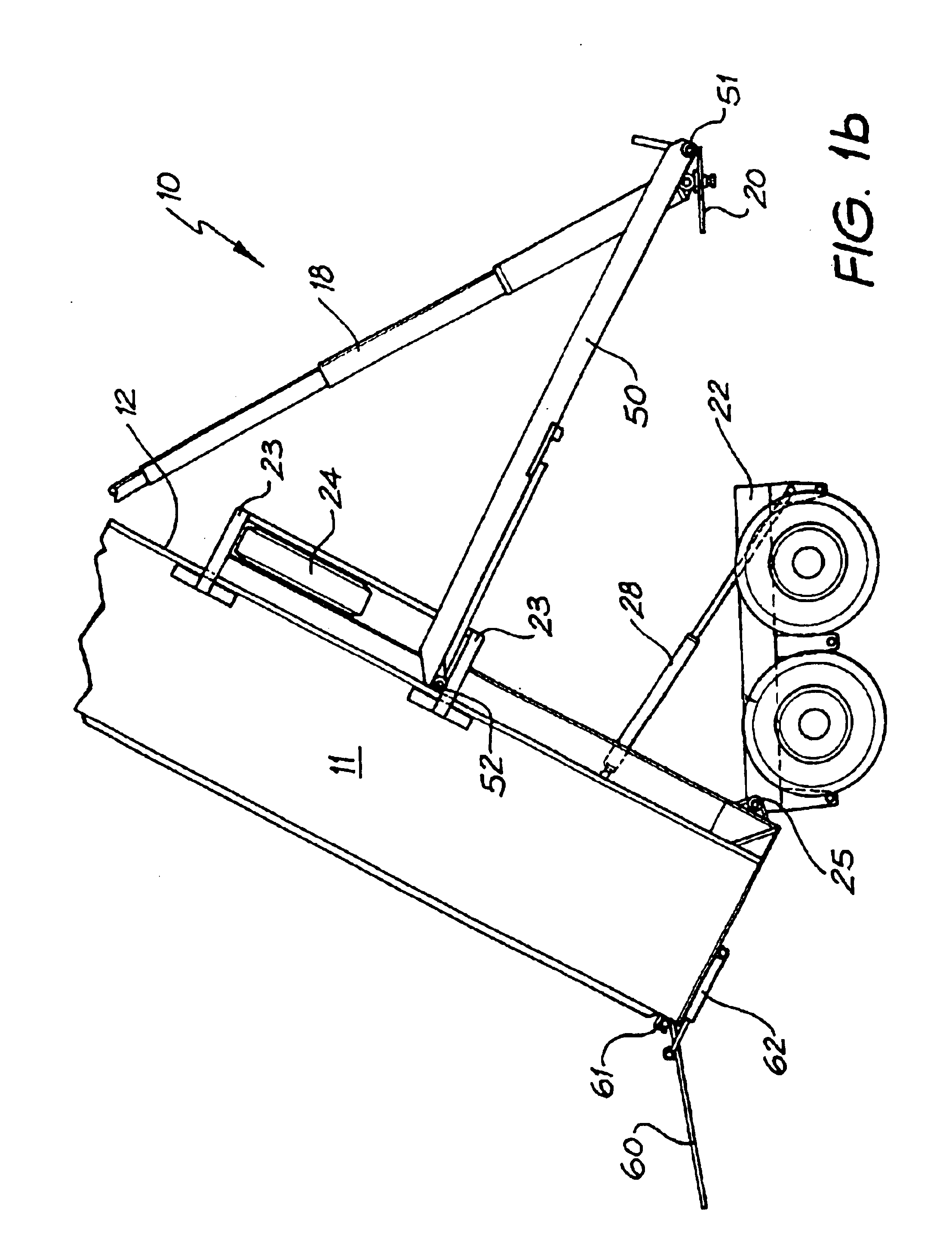
FIGS. 1a and 1b show a portion of a tip trailer 10 in accordance with the present invention. FIG. 1a shows a bin 11 of the tip trailer 10 in a travel position, and FIG. 1b shows a bin 11 of the tip trailer 10 in a tipped position. In accordance with the first aspect of the invention, the bin 11 of the tip trailer 10 has a floor 12, a front wall 13, two side walls and a plurality of struts 21 (refer to FIG. 2b) extending from the floor 12 to the upper extremity of the side walls. The tip trailer 10 further includes two front axles (not shown) and corresponding front wheels (not shown) and two rear axles 16 and corresponding rear wheels 17. Tipping means 18 are operable to tip the bin 11, as shown in FIG. 1b. In the embodiment of the invention shown in FIGS. 1a and 1b, the tipping means 18 is a hydraulic ram. The tip trailer further includes overhead beams 19 which are located substantially at an upper extremity of each side wall of the bin 11, and which extend substantially along a l...


PUM


Abstract

A tip trailer (10) includes a bin (11) having a floor (12), a front wall (13), side walls, a plurality of struts extending from the floor (12) to substantially an upper extremity of the side walls, one or more rear axles (16) and wheels (17), and one or more hydraulic rams (18, 28) operable to tip the bin (11), wherein overhead beams (19) are located substantially along a length of the bin (11), and the floor (12) is suspended from the overhead beams (19).

Description

The present invention relates to tip trailers, and in particular provides a low profile and lightweight tip trailer.Tip trailers are regularly used in a wide range of applications, primarily in the earthmoving industry. For example, tip trailers may be used for transporting materials in civil contracting works such as construction or road works, or may be used to remove workings from a mine, or to deliver soil to private individuals such as landholders or farmers.Conventional tip trailers usually lift a front end of a bin to cause a load to slide out a back of the truck, or, in the case of a `side tipper`, a side of the bin is lifted to cause the load to slide out an opposite side of the bin. Conventional tip trailers are usually of one of the following two types: "chassis tipper" or "tip-over-axle". A chassis tipper is characterised by a chassis mounted on front and Year axles, the bin being mounted on the chassis such that when tipped, a front end of the bin rises, above the chass...

Claims


Application Information

Patent Timeline
Patent Type & Authority Patents(United States)
IPC IPC(8): B62D53/00B60P1/16B60P1/04B60P1/28B62D53/06
CPCB60P1/16B60P1/165B60P1/286B62D53/062
Inventor MATHEWS, MARK
Owner MATHEWS MARK
Why Eureka
Try Eureka