Method for darkness correction of trapped pixels

a technology of dark correction and pixels, applied in the field of methods for correcting the characteristics of marking engines, can solve the problem that the color uniformity cannot be maintained near the edges

Inactive Publication Date: 2008-03-04
XEROX CORP
View PDF11 Cites 7 Cited by
  • Summary
  • Abstract
  • Description
  • Claims
  • Application Information

AI Technical Summary

Benefits of technology

[0009]The method of the invention corrects for marking engine characteristics associated with edges in an image. In many marking engines, color uniformity cannot be maintained near edges; this presents a significant problem for trapping. The method may be used to correct trap pixels generated by a trap engine associated with the print engine. If the edge region is determined by a trap engine associated with the print, the method further includes building a trap correction lookup table; building an edge correction table for each color in the desired set of colors; and using the edge correction table to adjust the trap correction lookup table. The method applies a correction to trap pixels using one or more mechanisms, including either a lookup table or an analytic correction. The correction may be determined empirically. The trap engine correction table could be modified and thus could be used directly to effect the correction, however, a separate correction table may also be used. A separate correction table could be applied to each color separation since the several color markers may have different edge rendering characteristics. The method takes into account edge effects of the marker, as well as the colors of adjoining image areas.

Problems solved by technology

In many marking engines, color uniformity cannot be maintained near edges; this presents a significant problem for trapping.

Method used


Image

  • Method for darkness correction of trapped pixels
  • Method for darkness correction of trapped pixels
  • Method for darkness correction of trapped pixels

Examples


Embodiment Construction

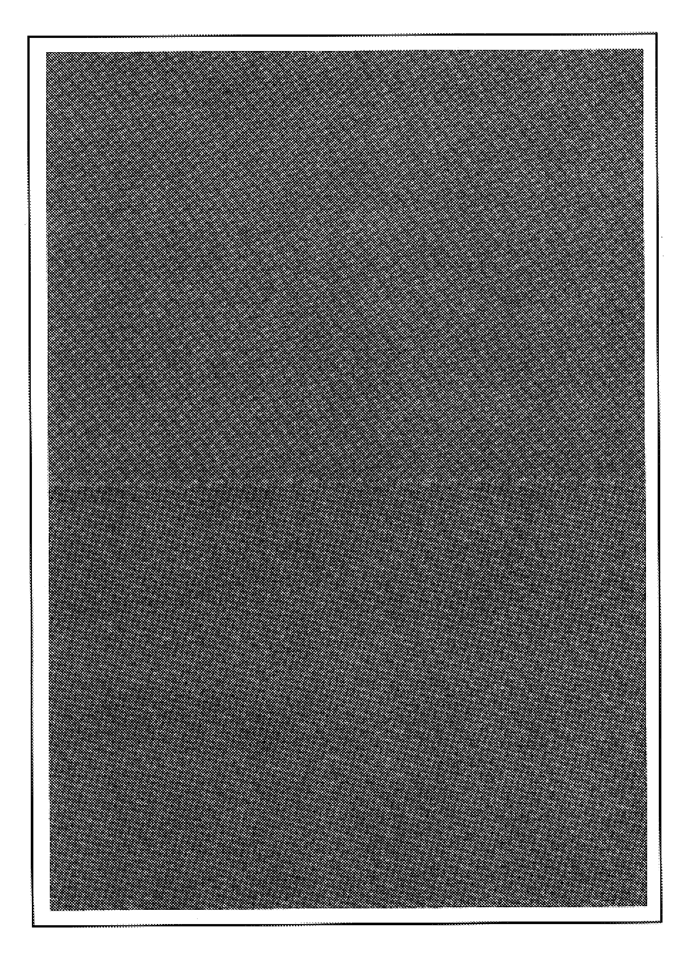
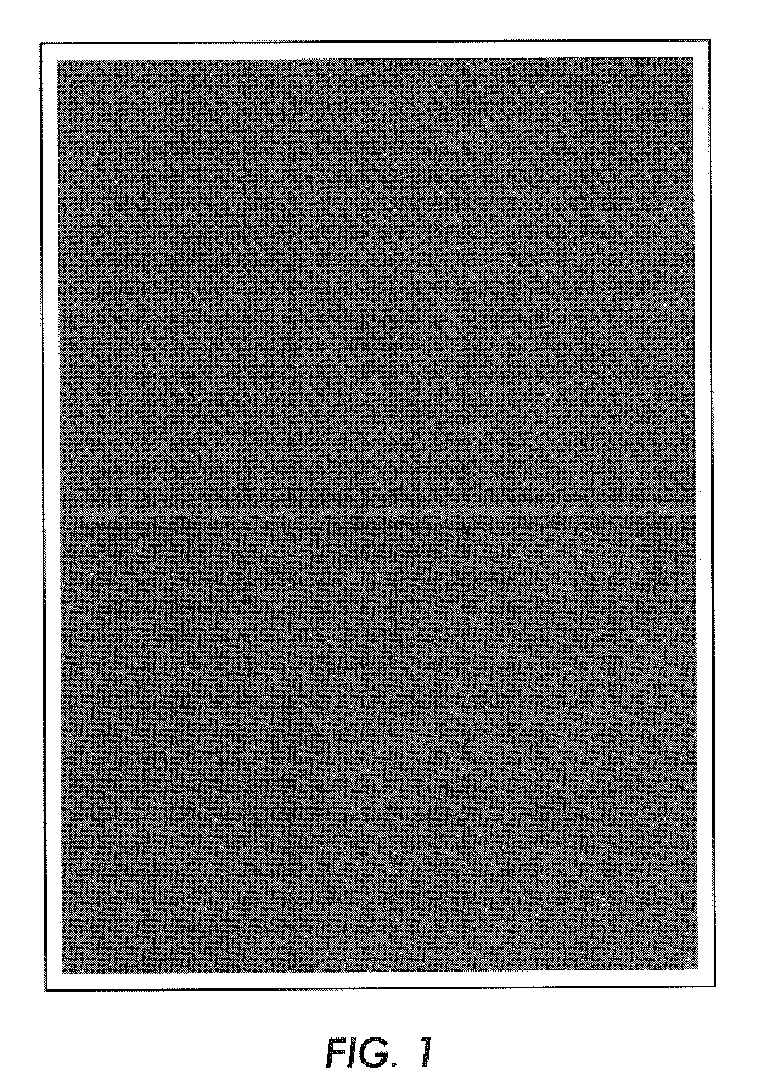
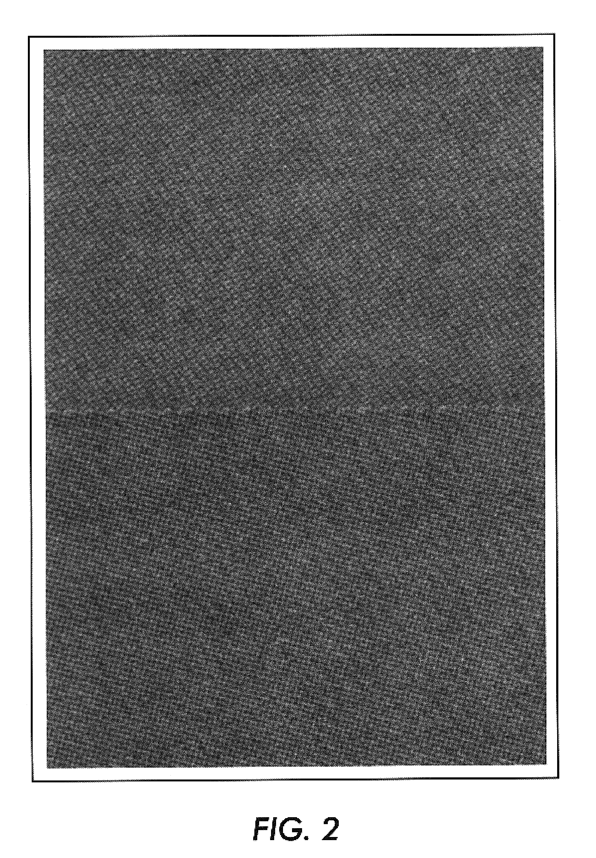
[0013]The method of the invention corrects for edge defects caused by print characteristics of a print engine. FIG. 1 is an example of an image showing the differences in color output at the edge of the image compared to a uniform area region of the image. The edge defects are caused by the print characteristics of the marking system. FIG. 2 is an example of the image of FIG. 1 which has been corrected according to a method for correcting for edge defects caused by print characteristics of a print engine. The method of the invention may be used for color correction of trapped pixels.

[0014]A trap engine or trap oracle corrects for edge defects caused by misregistration of the various separations. The trap engine predetermines the best trap color based on the colors associated with the abutting objects, and the color characteristics of the marking system. The method of the invention provides a color correction for marking system characteristics that cause colors to print differently o...


PUM


Abstract

A method for correcting for edge defects caused by print characteristics of a print engine includes printing a set of actual color patches corresponding to a desired set of colors; defining an edge region and a uniform area region in each of the patches; for each color patch in the set of actual color patches: determining a difference between color in the edge region of the patch and color in the uniform area region of the patch; and generating an edge response to adjust color output of the print engine in the edge region to substantially match color output in the uniform area region. The method can perform edge correction for any edge region of an image. In one embodiment of the invention, the edge region may be determined by a trap engine associated with the print engine and the method can provide correction for trap pixels.

Description

FIELD OF THE INVENTION[0001]This invention relates generally to methods for correcting for marking engine characteristics, and more particularly, to a method for correcting for edge modulations caused by the marking engine characteristics in order to achieve traps that are more visually pleasing.BACKGROUND OF THE INVENTION[0002]Electronic processing of graphic and text images produces multi-color prints using multiple color separations. Typically, four process colors, cyan, magenta, yellow and black, are used to print multiple separations, which tend to have minor misregistration problems. The result of abutting or overlapping shapes is a boundary between adjacent regions of color that, under ideal printing conditions should have zero width. That is, one color should stop exactly where the abutting color begins, with no new colors being introduced along the boundary by the printing process itself. The “colors” which fill the shapes can be solid colors, tints, degrades, contone image...

Claims


Application Information

Patent Timeline
Patent Type & Authority Patents(United States)
IPC IPC(8): H04N1/50H04N1/58
CPCH04N1/58
Inventor MCELVAIN, JON S.
Owner XEROX CORP
Why Eureka
Try Eureka