Variable voltage supply system

a voltage supply system and variable voltage technology, applied in the direction of motor/generator/converter stopper, dynamo-electric converter control, instruments, etc., can solve the problems of unnecessary current drawn from the supply, large transformer and high cos

Active Publication Date: 2009-12-17
ORTEA SPA
View PDF9 Cites 5 Cited by
  • Summary
  • Abstract
  • Description
  • Claims
  • Application Information

AI Technical Summary

Benefits of technology

[0010]An aspect of some embodiments of the present invention is concerned with supplying a varying voltage to a load, whereby more than two different voltages are provided to to the load, without the use of active elements and without substantial commutation problems.

Problems solved by technology

This causes unnecessary currents to be drawn from the supply (line).
This method suffers from a number of different deficiencies.
A second deficiency is that the coil and core of the transformer must be designed to carry the starting current of the motor.
This makes the transformer very large and expensive, with sizes similar to those of the motor itself being common.
A third deficiency is that there are serious commutation problems, since the output is disconnected each time the tap is changed.
This method does not deliver a sinusoidal voltage and its inefficiencies in starting motors are well known.
In particular, there is an intrinsic phase delay, especially during start-up and power robbing transients when the thyristor fires.
Furthermore, it is generally not possible to use capacitors for improvement of power factor with phase control.
Another issue that arises with control of induction motors is that they are most efficient at full load.
When the load is reduced, the core losses remain high and the efficiency drops.
However, no practical way of implementing such change is known.

Method used


Image

  • Variable voltage supply system
  • Variable voltage supply system
  • Variable voltage supply system

Examples


Embodiment Construction

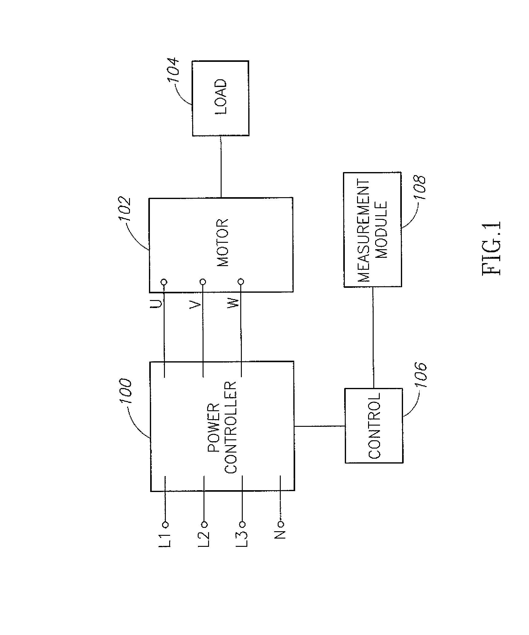
[0068]FIG. 1 is a schematic circuit drawing of a power controller (drive system) 100 powering a motor 102, in accordance with an exemplary embodiment of the invention. As shown, power controller 100 receives three phase power at phases L1, L2 and L3 at a first voltage and delivers power to motor 100 at a variable output voltage at phases U, V and W. The motor drives a load 104. A neutral N may be supplied to the motor. A controller 106 controls the operation of the power controllers and may be responsive to inputs from an optional measurement module 108, as explained below.

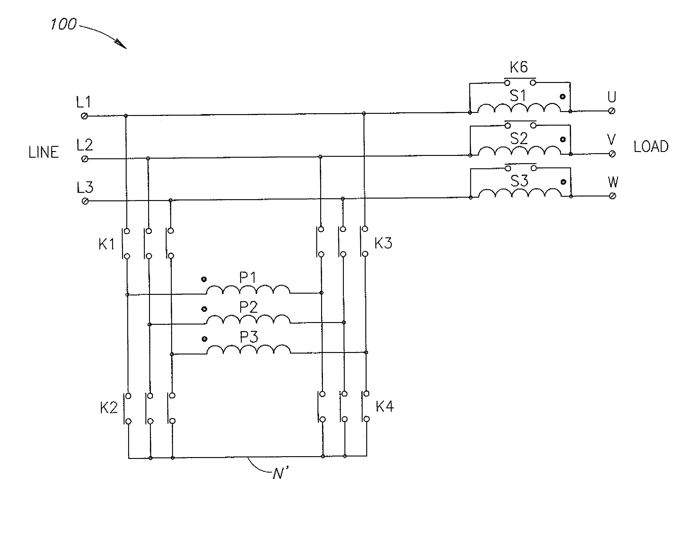
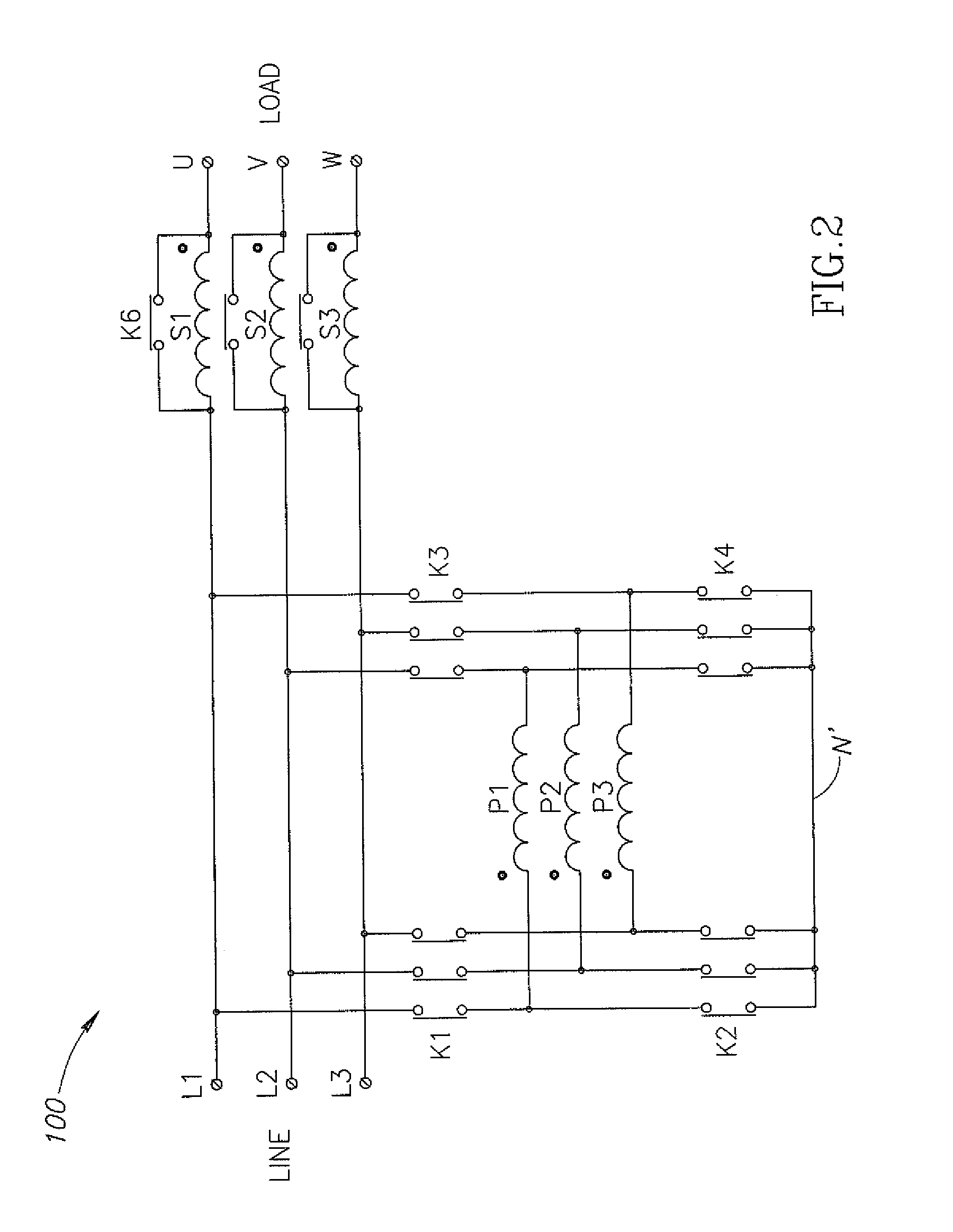
[0069]FIG. 2 shows some details of circuitry of power controller 100, in an exemplary embodiment of the invention. In its simplest form the power controller comprises a three phase transformer having first windings designated as P1, P2 and P3 and secondary windings S1, S2 and S3. The secondary windings are connected in series between the line inputs and the load. In addition, the power controller includes a plural...


PUM


Abstract

Apparatus for controlling the voltage supplied to a load, comprising:
a multi-phase transformer having a primary and a secondary winding for each phase, each secondary being connected in series between an input line and an output directed to the load; and
the primary is configurable by switches such that the phase of the voltage of the secondary is different from the line to which it is connected by a phase different from 0 and 180 degrees.

Description

FIELD OF THE INVENTION[0001]The present invention is concerned with providing a variable voltage, for example a variable voltage system suitable for starting a motor and for running a motor under reduced load.BACKGROUND OF THE INVENTION[0002]Induction motors supply a back EMF voltage when they are running. During start-up, with no back EMF, the input impedance of the motors is relatively low and the surge voltage is high. This causes unnecessary currents to be drawn from the supply (line). Not only does this require that the motor be designed to withstand these lines, the line must have these large currents available.[0003]A number of solutions have been proposed and are in use for providing a lower voltage during start-up and increasing the voltage as the speed of the motor increases.[0004]One method is the “star-delta” configuration in which the motor is fed from a three phase transformer and the windings of the motor are switched from a star connection to the power line to a delt...

Claims


Application Information

Patent Timeline
Patent Type & Authority Applications(United States)
IPC IPC(8): G05F5/00H02P27/00
CPCH02P25/16H02P21/146H02P21/18H02P27/02
Inventor LIMOR, SHIMON
Owner ORTEA SPA
Why Eureka
Try Eureka