Capillary for optical fiber and ferrule for optical connector for reducing connection loss

a technology of optical fiber and ferrule, which is applied in the direction of optics, optical elements, instruments, etc., can solve the problems of increasing light signal loss, increasing the manufacturing cost of ferrules, and extraordinary cumbersome actual core adjusting operation

Inactive Publication Date: 2004-07-13
NIPPON ELECTRIC GLASS CO LTD
View PDF5 Cites 6 Cited by
  • Summary
  • Abstract
  • Description
  • Claims
  • Application Information

AI Technical Summary

Benefits of technology

Since the capillary for optical fiber according to the present invention has the inner hole having the surface roughness Ra value of 0.1 .mu.m to 0.5 .mu.m, due to the affection of the peaks higher than the average line and dispersed on the inner hole surface, the adhesive, including the epoxy-type one with proper viscosity, spreads uniformly in the circumferential direction to be retained on the surface of the inner hole in a stable manner, holding the optical fiber in the central position of the inner hole.
Also, the inner hole of the capillary for optical fiber of the present invention has the surface roughness Ry value of 4.0 .mu.m or less, which prevents the center of the maximum inscribed cylinder of the inner hole from decentered against the center of the circle determined by the average line of the surface roughness of the inner hole. This fact ensures that a high circularity of the inner hole and the concentricity between the inner hole and the outer periphery of the capillary are retained so that a desired core adjusting effect is obtained and the surface of inserted optical fiber is not damaged.
Further, in the capillary for optical fiber of the present invention, the difference between the average line and the peak line of the surface roughness in the inner hole is 2.0 .mu.m or less. Because of this fact, the center of the maximum inscribed cylinder of the inner hole is not decentered against the center of the circle determined by the average line of the surface roughness of the inner hole, even if the peaks and valleys of the surface roughness are not symmetrically with each other with respect to the average line of the surface roughness, so that the high circularity of the inner hole and the concentricity between the inner hole and the outer periphery of the capillary is secured and the surface of inserted optical fiber is not damaged. Thus, the desired core adjustment effect is obtained.
The capillary for optical fiber of the present invention is made of crystallized glass formed by precipitating crystals in amorphous glass. The crystallized glass is subjected to a heat treatment under a proper condition to precipitate crystallized grains on the surface of the inner hole, where the grains form the peaks. This process enables easy, effective manufacturing of the capillary having the inner hole with the surface roughness Ra value of 0.1 .mu.m to 0.5 .mu.m, the capillary having the inner hole with the surface roughness Ra value of 0.1 .mu.m to 0.5 .mu.m and Ry value of 4.0 .mu.m or less, the capillary having the inner hole with the surface roughness Ra value of 0.1 .mu.m to 0.5 .mu.m and the difference between the average line and the peak line of 2.0 .mu.m or less, and the capillary having the inner hole with the above surface roughness Ra and Ry values and the difference between the average line and the peak line of 2.0 .mu.m or less.
In the capillary for optical fiber of the present invention, the inner hole has a prescribed surface roughness formed by a mechanical process mean. Therefore, the inner hole with surface roughness Ra value of 0.1 .mu.m to 0.5 .mu.m, the capillary having the inner hole with the surface roughness Ra value of 0.1 .mu.m to 0.5 .mu.m and Ry value of 4.0 .mu.m or less, the capillary having the inner hole with the surface roughness Ra value of 0.1 .mu.m to 0.5 .mu.m and the difference between the average line and the peak line of 2.0 .mu.m or less, and the capillary having the inner hole with the above surface roughness Ra and Ry values and the difference between the average line and the peak line of 2.0 .mu.m or less, are manufactured under a room temperature by using the internal grinding (or polishing) machine and the like.
The ferrule for optical connector of the present invention is that the capillary for optical fiber as described above is formed with the chamfered part on one end thereof for guiding the ferrule into the sleeve and the flared part opened to the other end for guiding an optical fiber into the inner hole. Therefore, the optical fiber can be held precisely in the center of the inner hole of the ferrule for optical connector by the core adjusting effect produced by the above surface roughness of the inner hole of the invented capillary for optical fiber.
The optical-fiber-fixed capillary of the present invention comprises the capillary for optical fiber as described above and the optical fiber inserted and fixed into the inner hole of the capillary for optical fiber. Therefore, there is provided the optical-fiber-fixed capillary, in which the optical fiber is retained in the center of the inner hole by the core adjusting effect produced by the surface roughness of the inner hole.

Problems solved by technology

Actual core adjusting operation, however, tends to be extraordinary cumbersome.
In this case, the core adjusting operation can not be carried out due to the structural characteristics of the optical fiber stub 6, which makes it impossible to reduce the axial dislocation caused by the eccentricity of the optical fiber 8 in the inner hole 7a when the conventional zirconia ceramic capillary 7 for optical fiber is employed, so that the problem of increasing light signal loss remains.
As a result, the manufacturing cost of ferrules becomes higher.
The optical fiber stub 6 formed by processing an optical-fiber-fixed capillary, as shown in FIG. 12, has the PC connection part with the structure equal to that of the ferrule for optical connector, making it impossible to carry out the core adjusting operation when a low connector connection loss equal to the above is required, which leads also to a stricter accuracy requirement to raise the problem of a higher production cost.
In such a case, the center of the maximum inscribed cylinder of the inner hole is decenterd in many cases against the center of the circle determined by the average line of the surface roughness of the inner hole, so that the original concentricity of the inner hole virtually deteriorates, or the surface of the inserted optical fiber may suffer scratches, raising a fear of decreasing strength of the optical fiber.
However, when the surface roughness Ra value exceeds 0.5 .mu.m, satisfying the above dimensional accuracy is difficult and mass production of optical connector plugs or optical fiber stubs becomes almost impossible.
Likewise, when an optical connector plug or optical fiber stub is comprised of a crystallized glass capillary for optical fiber manufactured by drawing forming, the surface roughness Ra value of over 0.5 .mu.m makes it difficult to satisfy the strict dimensional accuracy required for capillaries for an optical fiber stub, so that mass production of inexpensive optical fiber stubs becomes also difficult.
If this happens, the original concentricity of the inner hole virtually deteriorates and projected sharp peaks of the surface roughness of the inner hole may damage the surface of an inserted optical fiber.

Method used


Image

  • Capillary for optical fiber and ferrule for optical connector for reducing connection loss
  • Capillary for optical fiber and ferrule for optical connector for reducing connection loss
  • Capillary for optical fiber and ferrule for optical connector for reducing connection loss

Examples


Embodiment Construction

The inventors have used, for example, a crystallized glass capillary for optical fiber having the composition shown in a table 1 as one example of the capillaries for optical fiber according to the present invention.

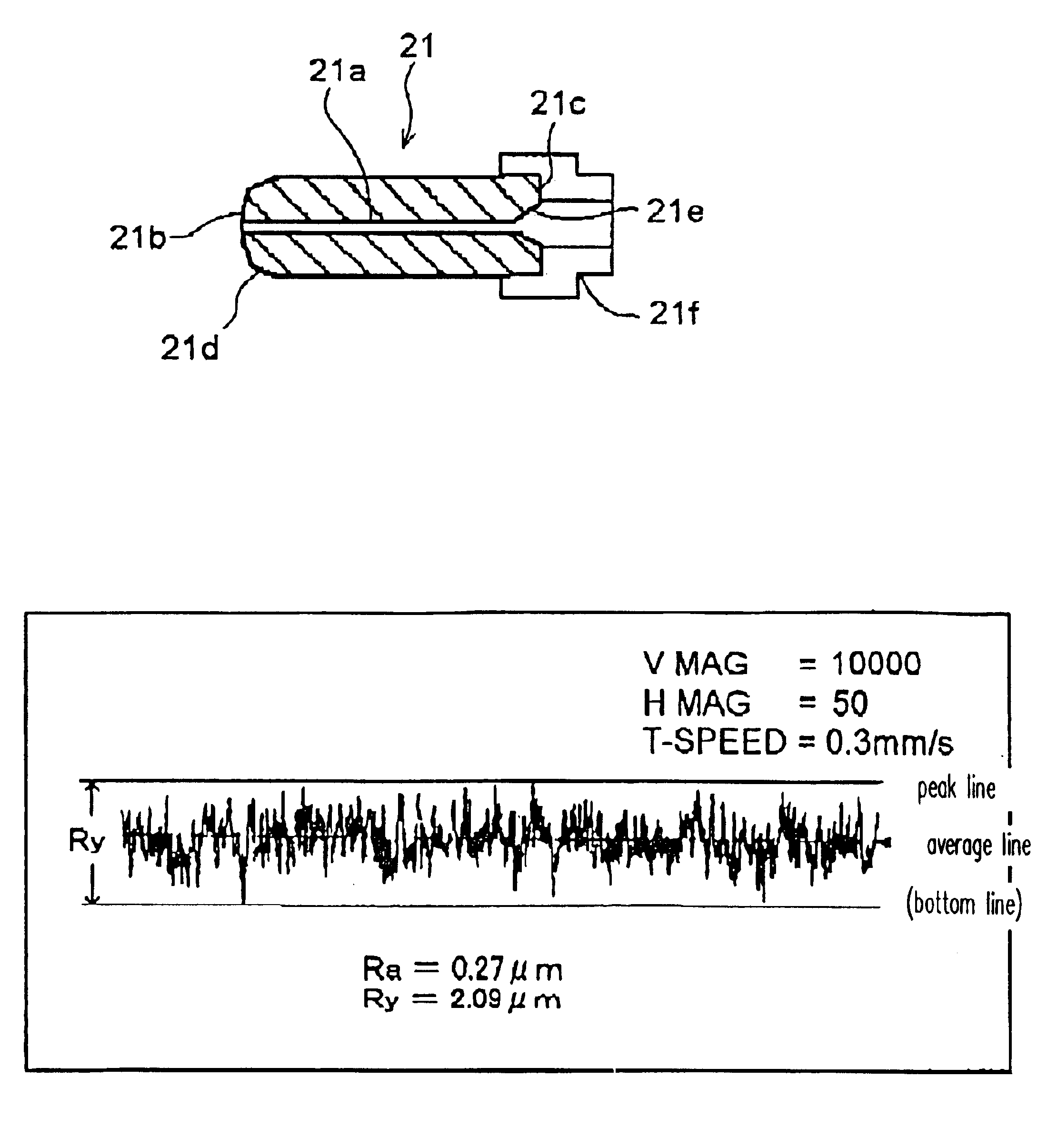
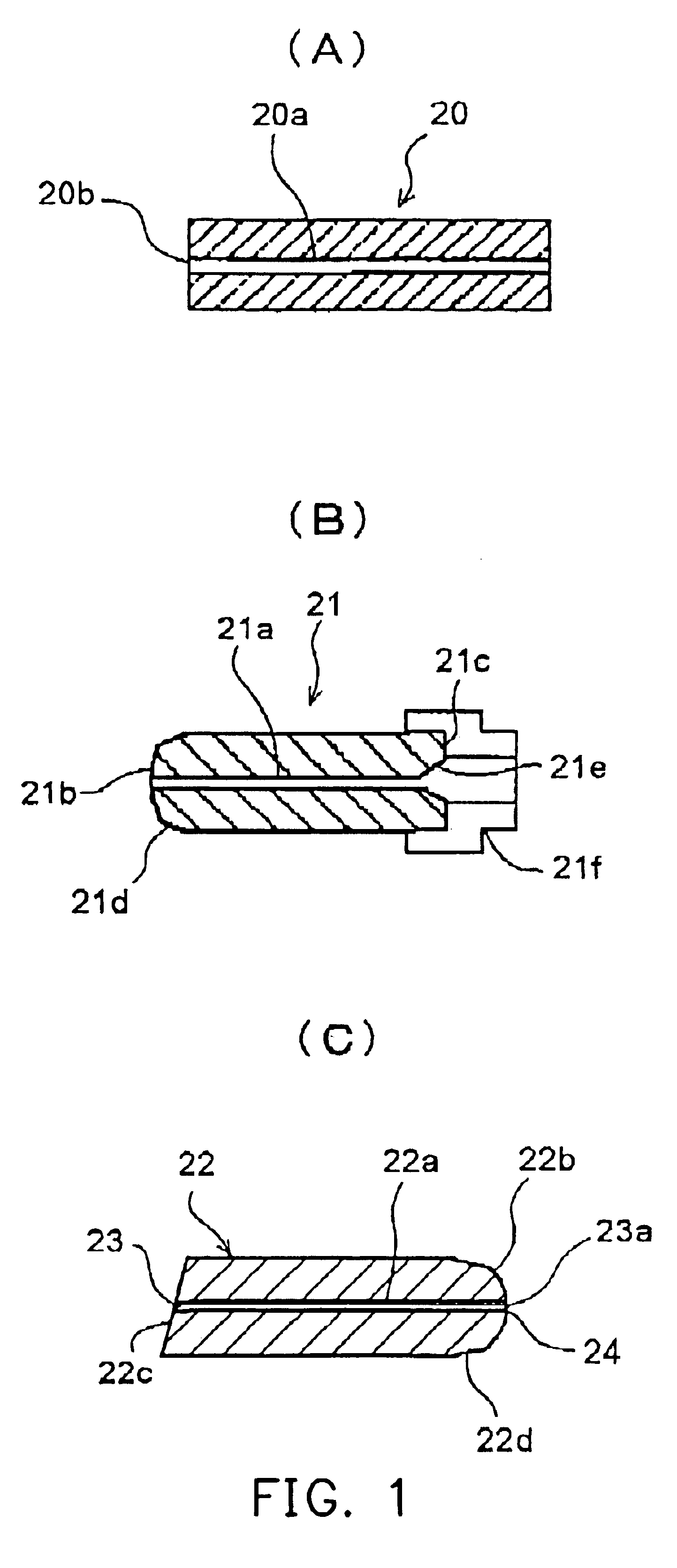
As shown FIG. 1 (A), the crystallized glass capillary 20 for optical fiber is manufactured. The capillary 20 for optical fiber has an inner hole 20a with the surface roughness Ra value of, for example, approximately 0.3 .mu.m, Ry value of approximately 2.0 .mu.m, the difference between the average line and the peak line of approximately 1.0 .mu.m, wherein the inner diameter of the inner hole is approximately 1.0 .mu.m (0.95 to 1.05 .mu.m) larger than the outer diameter of an optical fiber to be inserted.

The ferrule 21 for optical connector shown in FIG. 1 (B) has been manufactured using the capillary for optical fiber 20. The manufactured ferrule 21 for optical fiber can be connected to an optical connector plug with a prescribed connection loss. For example, the ferrule...


PUM

PropertyMeasurementUnit
surface roughnessaaaaaaaaaa

Abstract

The capillary for optical fiber has an inner hole allowing an optical fiber to be inserted and retained therein. Ra value of the surface roughness of the inner hole is 0.1 mum to 0.5 mum. The ferrule for optical connector is provided with a chamfered part on one end of the capillary for optical fiber for guiding it into a sleeve and a flared part on the other end of the capillary for optical fiber for guiding the optical fiber into the inner hole.

Description

This application claims the priority benefit of Japanese application serial no. 2001-352986, filed on Nov. 19, 2001.BACKGROUND OF INVENTIONThe present invention relates to a capillary for optical fiber, a ferrule for optical connector, and an optical-fiber-fixed capillary in which an optical fiber is inserted and fixed into an inner hole of a capillary for optical fiber, which are used for manufacturing optical devices.Recent rapid development of optical communication networks has raised the need for large quantities of high performance, inexpensive optical devices. For a plug-type optical device or a receptacle-type optical device with a built-in optical fiber, in particular, a cylindrical optical-fiber-fixed capillary, called optical fiber stub, formed by inserting an optical fiber into an precise capillary to be fixed with an adhesive, and an optical connector plug are employed.For example, as shown in FIG. 12, when one end face of an optical-fiber-fixed capillary is ground into ...

Claims


Application Information

Patent Timeline
Patent Type & Authority Patents(United States)
IPC IPC(8): G02B6/38G02B6/42G02B6/36G02B6/40
CPCC03C10/00G02B6/3863G02B6/3822G02B6/3837G02B6/3861G02B6/421
Inventor WADA, MASANORITAKEUCHI, HIROKAZUSAITO, KAZUYA
Owner NIPPON ELECTRIC GLASS CO LTD
Why Eureka
Try Eureka