
White light source and display apparatus using the same

a technology of white light source and display apparatus, which is applied in the direction of identification means, instruments, discharge tubes, etc., can solve the problems that the conventional single phosphor material does not meet all the required characteristics and cannot yield a sufficient color temperatur

Inactive Publication Date: 2004-07-13
HITACHI LTD
View PDF12 Cites 26 Cited by
  • Summary
  • Abstract
  • Description
  • Claims
  • Application Information

AI Technical Summary

Benefits of technology

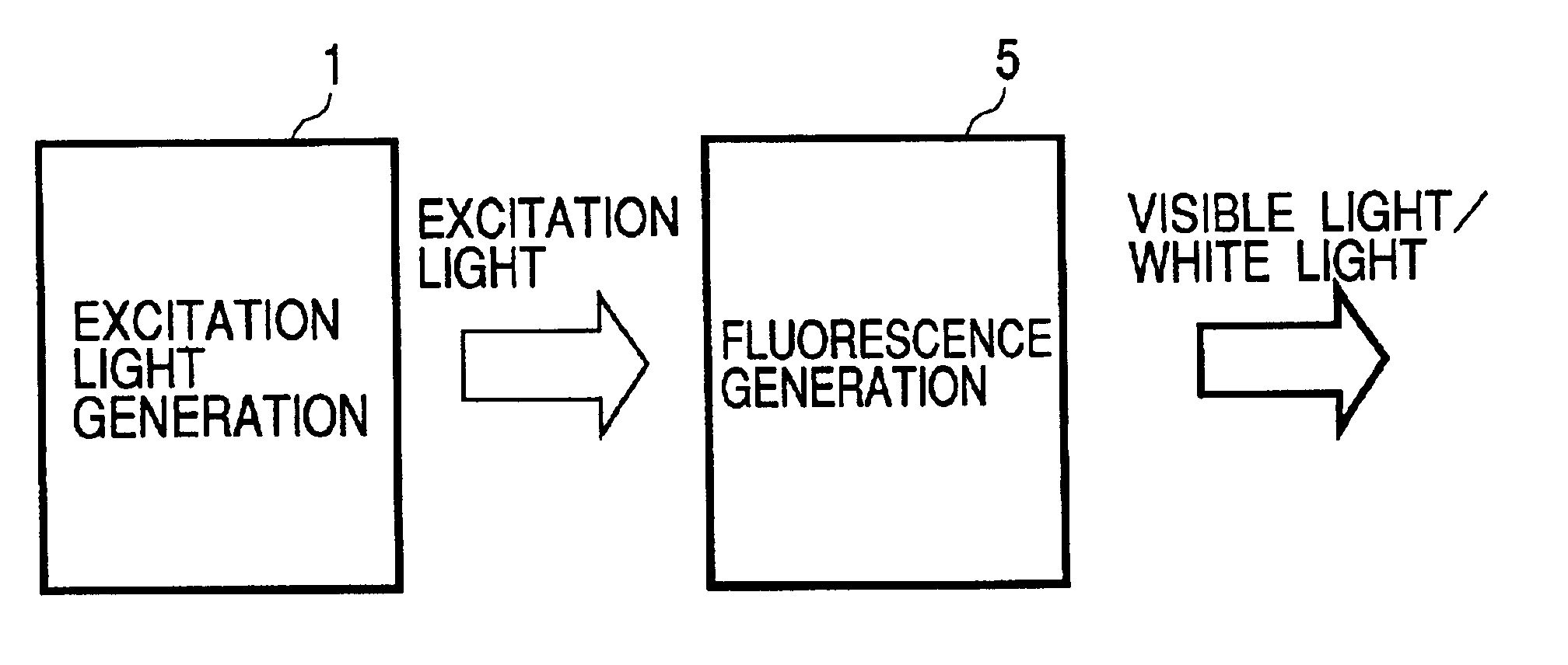
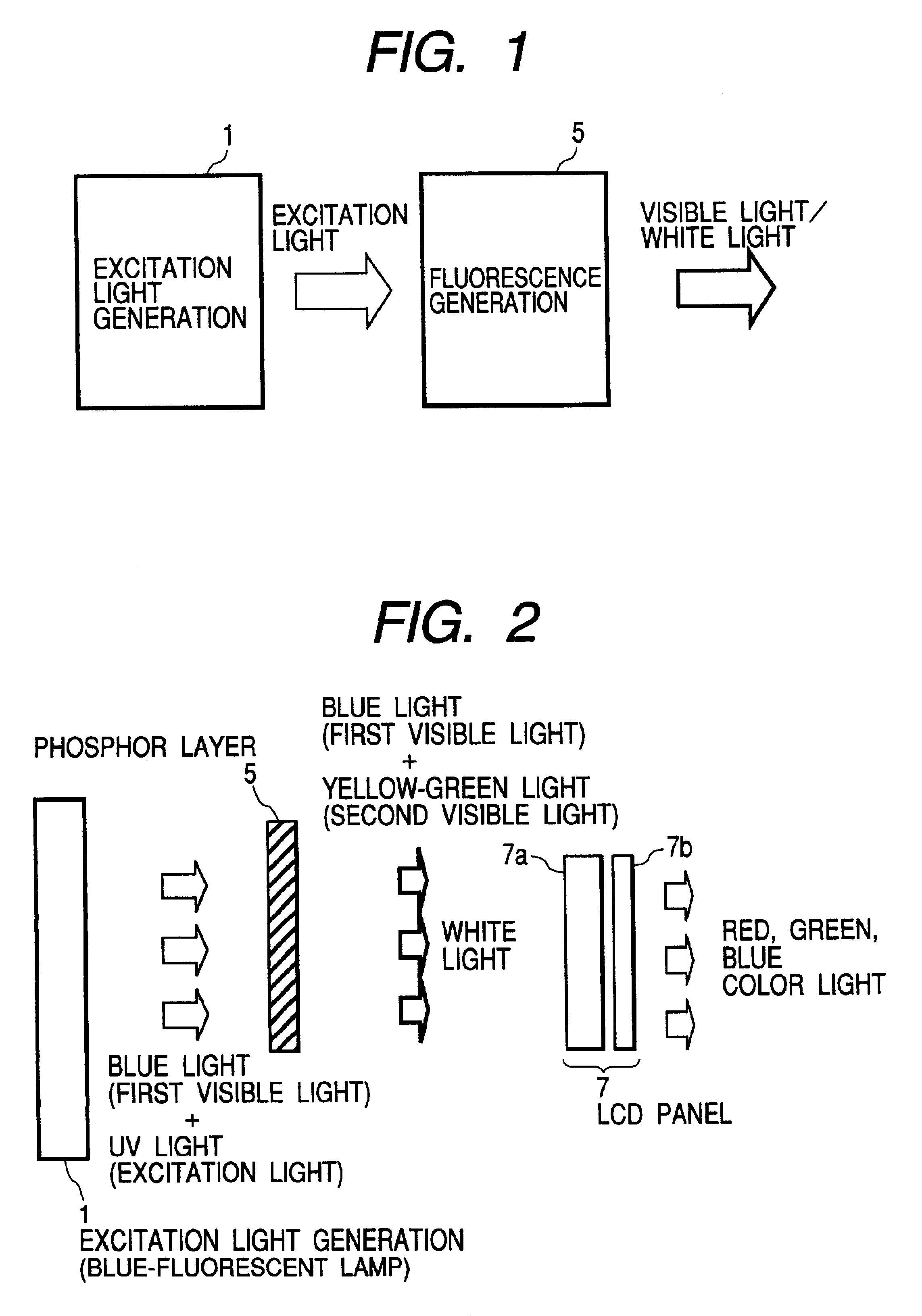
Accordingly, an object of the present invention is to solve the above problems and to provide a high-quality white light source capable of emitting an increased red light component in addition to luminous colors of the conventional Y.sub.3 (Al,Ga).sub.5 O.sub.12 : Ce green light phosphor used in such light sources, as well as to provide a display apparatus using the white light source.

Problems solved by technology

However, no conventional single phosphor material has sufficiently satisfied all the required characteristics.
However, this phosphor cannot yield a sufficient color temperature.

Method used


Image

  • White light source and display apparatus using the same
  • White light source and display apparatus using the same
  • White light source and display apparatus using the same

Examples


second embodiment

To verify a preferred range of the Sr content a, a series of phosphors represented by Compositional Formula (1): (Ca.sub.1-a-b Sr.sub.a Eu.sub.b)S:M.sub.c, wherein a, b and c satisfy the following conditions: 0.ltoreq.a<1.0, 0

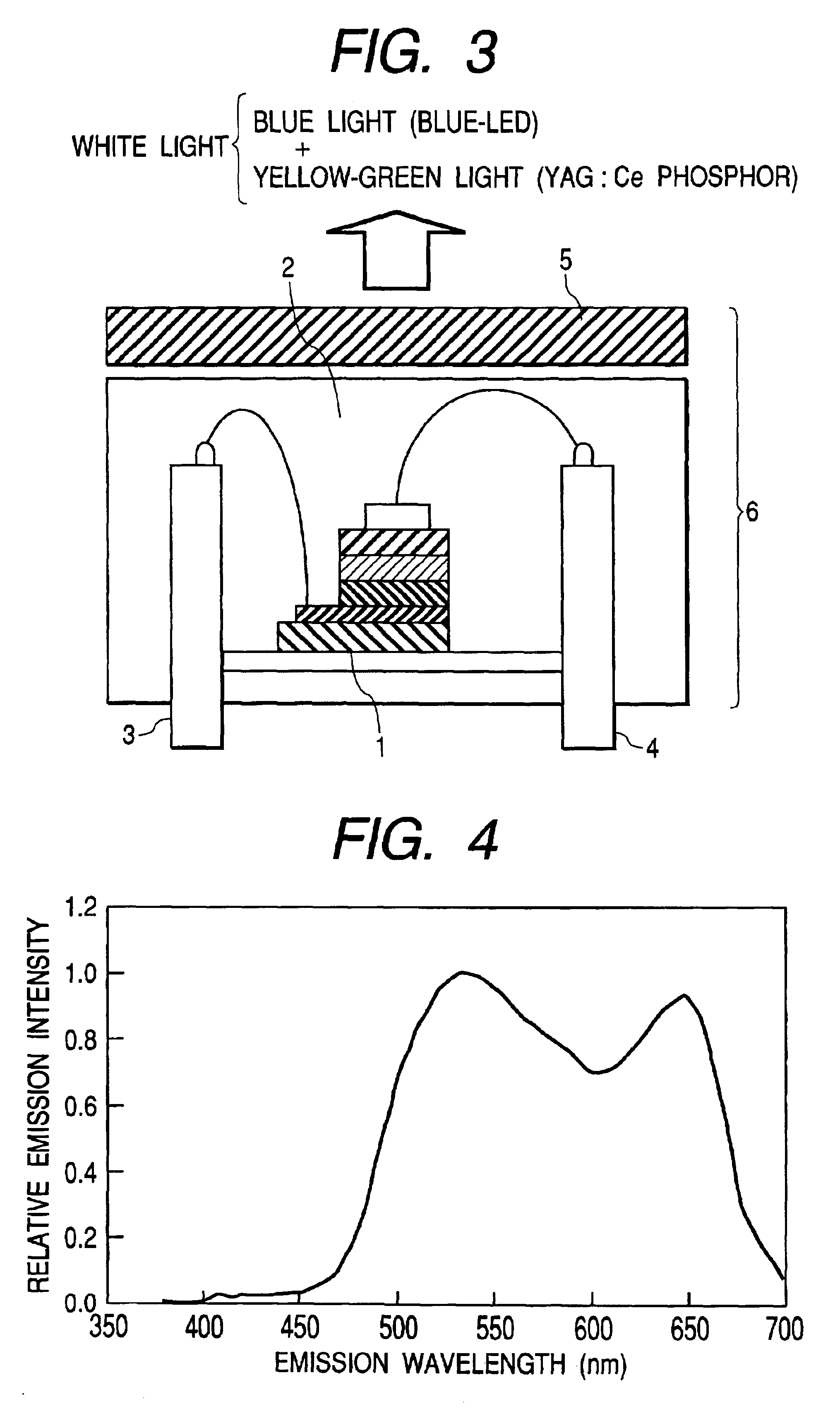
Using the above-prepared phosphors having different compositions represented by Compositional Formula (1), a series of phosphor layers were prepared. The excitation light emission characteristics of the phosphor layers were determined using the blue-LED that was used in First Embodiment and had the emission spectrum shown in FIG. 5.

In this procedure, the light source 6 having the configuration shown in FIG. 3 was used, where the blue-LED 1 and the phosphor layer 5 were separately disposed.

As a r...

third embodiment

To verify a preferred range of the Eu content b, a series of phosphors represented by Compositional Formula (1): (Ca.sub.1-a-b Sr.sub.a Eu.sub.b)S:M.sub.c, wherein a, b and c satisfy the following conditions: 0.ltoreq.a<1.0, 0

Using the above-prepared phosphors having different compositions represented by Compositional Formula (1), a series of phosphor layers were prepared. The excitation light emission characteristics of the phosphor layers were determined using the blue-LED that was used in First Embodiment and had the emission spectrum shown in FIG. 5.

In this procedure, the light source 6 having the configuration shown in FIG. 3 was used, where the blue-LED 1 and the phosphor layer constituting the fluorescence generation unit 5 were separately disposed.

The results show that ...

fourth embodiment

To verify a preferred range of the Ce dopant content c, a series of phosphors represented by Compositional Formula (1): (Ca.sub.1-a-b Sr.sub.a Eu.sub.b)S:M.sub.c, wherein a, b and c satisfy the following conditions: 0.ltoreq.a<1.0, 0<b.ltoreq.0.1 and 0.ltoreq.c.ltoreq.0.1, were prepared in the same manner as in First Embodiment, except that the Sr content a was fixed at 0, the Eu content b was fixed at 0.05 and the Ce dopant content c was varied within the range of 0.ltoreq.c.ltoreq.0.1.

Using the above-prepared phosphors having different compositions represented by Compositional Formula (1), a series of phosphor layers were prepared. The excitation light emission characteristics of the phosphor layers were determined using the blue-LED that was used in First Embodiment and had the emission spectrum shown in FIG. 5.

In this procedure, the light source 6 having the configuration shown in FIG. 3 was used, where the blue-LED 1 and the phosphor constituting the phosphor layer 5 were separ...


PUM

PropertyMeasurementUnit
wavelengthaaaaaaaaaa
fluorescenceaaaaaaaaaa
absorption of excitation energyaaaaaaaaaa

Abstract

A white light source includes an ultraviolet-visible excitation light generation unit capable of generating visible light and ultraviolet light, and a fluorescence generation unit having a phosphor layer and being capable of generating visible light upon excitation by the ultraviolet light and uses, in the phosphor layer, a red light emitting phosphor represented by the following compositional formula: (Ca1-a-bSraEub)S:Mc, wherein a, b and c satisfy the following conditions: 0<=a<1.0, 0<=b<0.1 and 0<=c<=0.1; and M is a dopant element having absorption of excitation energy at about 350 nm to about 500 nm. The dopant element M includes rare earth elements such as Ce, Yb, Gd and Tm. By substituting part of Ca and / or Sr with Zn, the white light source can exhibit further improved performances. The white light source exhibits an increased red light component as compared with light emitted from conventional (Y1-a-bGdaCeb)3(Al1-cGac)5O12 green light phosphors and is suitably used in display apparatus.

Description

1. Field of the InventionThe present invention relates to a white light source and a display apparatus using the white light source. Specifically, it relates to a high-quality white light source that is suitable as a light source of display apparatus and to a display apparatus using the white light source.2. Description of the Related ArtLiquid crystal displays comprising liquid crystals as display panels have practically been used as display apparatus. Such liquid crystal displays essentially require light sources (back-lights) to display color images on the liquid crystals.Demands have recently been made on further miniaturized and higher-quality light sources. To improve image quality of such liquid displays as display apparatus, white light emitted from the light sources must have further improved quality. To improve image quality and to increase luminance, the light sources must have optimized white-light temperature, improved luminance saturation, luminance degradation and dec...

Claims


Application Information

Patent Timeline
Patent Type & Authority Patents(United States)
IPC IPC(8): C09K11/77H01J1/00H01J1/63H01L33/00G02F1/13357C09K11/56C09K11/84G09F9/00G09F9/35H01L33/50
CPCC09K11/7731H01J1/63H01L33/502Y02B20/181Y02B20/00G02F1/1335
Inventor SHIIKI, MASATOSHIKOMATSU, MASAAKIOKAZAKI, CHOICHIROIMAMURA, SHINSUZUKI, TERUKI
Owner HITACHI LTD
Learn More