Shaft for light-weight golf clubs

a golf club and shaft technology, applied in the direction of golf clubs, pedestrian/occupant safety arrangements, vehicular safety arrangements, etc., can solve the problems of low strength and rigidity low strength of reinforcing fibers with high elasticity, etc., to prevent longitudinal cracking of materials and improve rigidity and strength.

Inactive Publication Date: 2004-07-27
MITSUBISHI RAYON CO LTD
View PDF14 Cites 26 Cited by
  • Summary
  • Abstract
  • Description
  • Claims
  • Application Information

AI Technical Summary

Benefits of technology

Additional layers can be added to the basic four layer structure discussed above. According to the invention, any number of layers can be added as long as the overall diameter and weight are in accordance with the invention. By adding the additional layers, the end of the shaft can be reinforced, diameters can be matched, rigidity and strength can be enhanced and the like.
There are no special restrictions on the thickness of the first angled layer (1) as long as the thickness is a standard value generally used in FRP shafts. In a preferred embodiment, a thickness in the range of from 0.2-0.4 mm is desirable to prevent longitudinal cracking of the mate

Problems solved by technology

These reductions in strength and rigidity are undesirable.
However, reinforcing fibers with high elasticity generally have low strength.
However, the increased grip diameter results in a golf club shaft that is difficult to handle, making the arrangement impractical.
However, the finishing process of the FRP shaft, i.e., polishing and the like, can result in a loss in the angled layer.
Thus, FRP shafts made according to this method d

Method used


Image

  • Shaft for light-weight golf clubs
  • Shaft for light-weight golf clubs
  • Shaft for light-weight golf clubs

Examples


embodiment 1

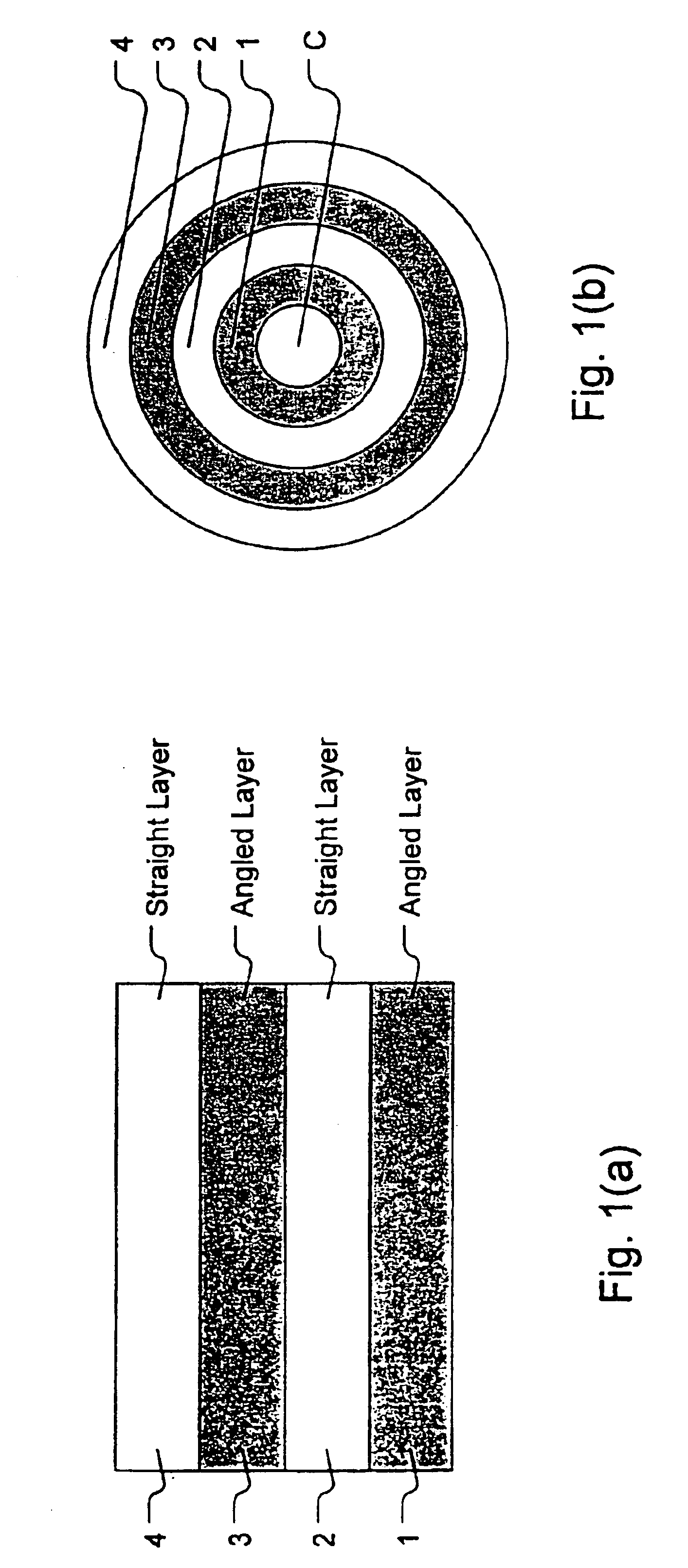
(1) A 90-degree reinforcing layer is formed as in step 1 of embodiment 1 discussed above (prepreg D in Table I).

(2) A first angled layer is formed as in step 2 of embodiment 1 discussed above (prepreg A in Table I).

(3) A first straight layer is formed as in step 3 of embodiment 1 discussed above (prepreg B in Table I).

(4) Two prepregs are each formed from single layers of fiber material (prepreg C in Table I). The fibers contained in the first prepreg are oriented at an angle of +20 degrees relative to the longitudinal axis of the shaft. The fist prepreg is sheared so that a single layer is formed at both the small-diameter end and the large-diameter end of the material. The second prepreg contains fibers that are oriented at an angle of -20 degrees relative to the longitudinal axis of the shaft. The second prepreg is sheared in same manner as the first prepreg. The two sheared prepregs are adhesively bonded together to form a single bonded material, such that the fibers from the tw...

embodiments 2-4

In embodiments 2-4 and comparative examples 3-4, the prepreg used to form the first angled layer is changed from prepreg A to prepreg G (see Table I). The second angled layer is formed from prepreg C. Each angled layer is formed by adhesively bonding two prepregs together as in step 4 of embodiment 1. The fiber orientation of the two prepregs used in each embodiment is described below.

embodiment 2

In embodiment 2, the second angled layer is replaced with an angled layer consisting of two prepreg layers which are oriented at angles of + / -45 degrees respectively.


PUM

PropertyMeasurementUnit
Weightaaaaaaaaaa
Fractionaaaaaaaaaa
Thicknessaaaaaaaaaa

Abstract

A golf club shaft is 35-50 percent lighter than a conventional shaft while maintaining the outer diameter and structural characteristics of conventional shafts. The shaft has at least four layers of fiber reinforced material. The fiber reinforced layers are from innermost to outermost: a first angled layer; a first straight layer; a second angled layer; and a second straight layer. The angled layers are formed by bonding together two materials, each with fibers aligned in different directions. The second angled layer maintains the proper strength and rigidity of the shaft while keeping the shaft as light weight as possible. Aligning the second layer's fibers at an angle of 35-75 degrees with respect to the longitudinal direction of the shaft ensures proper weight and strength characteristics of the shaft. The resulting shaft is light-weight and exhibits the flexural rigidity, flexural strength, torsional rigidity, torsional strength, and crushing strength of conventional shafts.

Description

The present invention relates to a shaft for golf clubs (hereinafter referred to simply as shaft). More specifically, the present invention relates to a shaft that is 35-50 percent lighter than conventional shafts while providing the same outer diameter and the same characteristics as conventional shafts such as flexural rigidity, flexural strength, torsional rigidity, torsional strength, and crushing strength.In one type of golf club, a fiber-reinforced composite material (hereinafter referred to as FRP) is used in forming the shaft. In this type of shaft, a fiber-reinforced fiber material is formed by lining up reinforcing fibers in a "one-directional" pre-impregnation (hereinafter referred to as prepregs) and then immersing the aligned fiber material in a resin. The shaft is then formed by wrapping the fiber-reinforced material around a tapered metal mandrel and hardening the composite in a laminated state. This type of golf club shaft is widely used due to its high specific rigi...

Claims


Application Information

Patent Timeline
IPC IPC(8): A63B53/10
CPCA63B53/10A63B59/0014Y10T428/1362A63B2209/023Y10T428/1352A63B2209/02A63B60/10A63B60/06A63B60/08A63B60/00A63B60/42
Inventor ATSUMI, TETSUYATAKIGUCHI, IKUOIBUKI, TSUTOMUANAI, KATSUMI
Owner MITSUBISHI RAYON CO LTD
Why Eureka
Try Eureka