Ionizer

Inactive Publication Date: 2004-08-03
MOTOUCHI KAZUO +2
View PDF20 Cites 16 Cited by
  • Summary
  • Abstract
  • Description
  • Claims
  • Application Information

AI Technical Summary

Problems solved by technology

Unfortunately, the ionization electrode I of FIG. 10 suffers a poor air-ionization efficiency because a majority of the corona discharge develops from the star electrodes 82b at the opposite ends of the shaft 82a while the other star electrodes 82b between these electrodes do not function effectively.
This results in an increased power consumption.
In addition, this electrode also suffers the same drawbacks as the ionization electrode I of FIG. 10.
That is, the discharge concentrates on one place due to the working errors or mounting errors of the electrodes, resulting in the burn of the electric circuit component and the like.
Even if the discharge does not concentra

Method used


Image

  • Ionizer
  • Ionizer
  • Ionizer

Examples


first embodiment

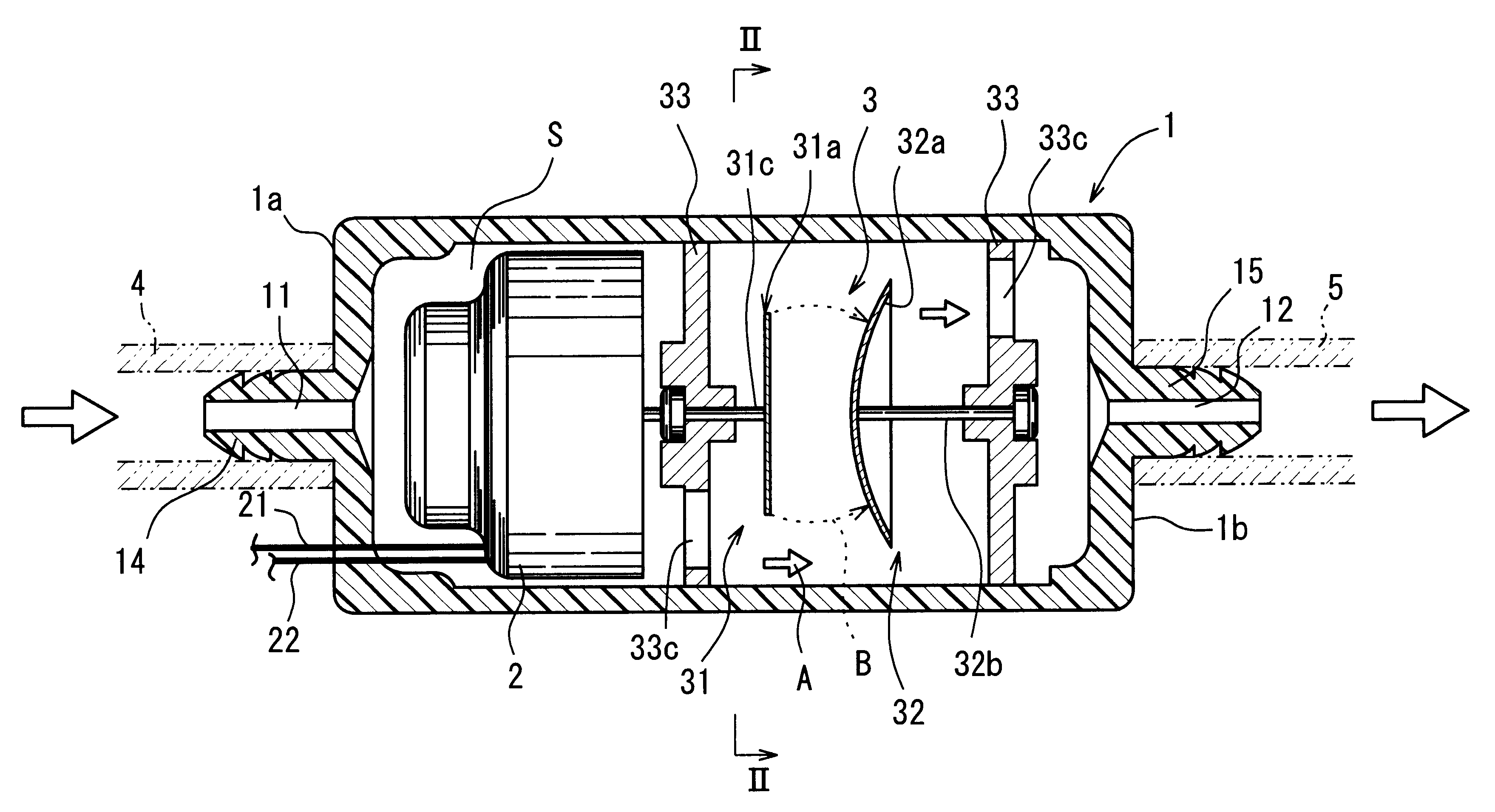
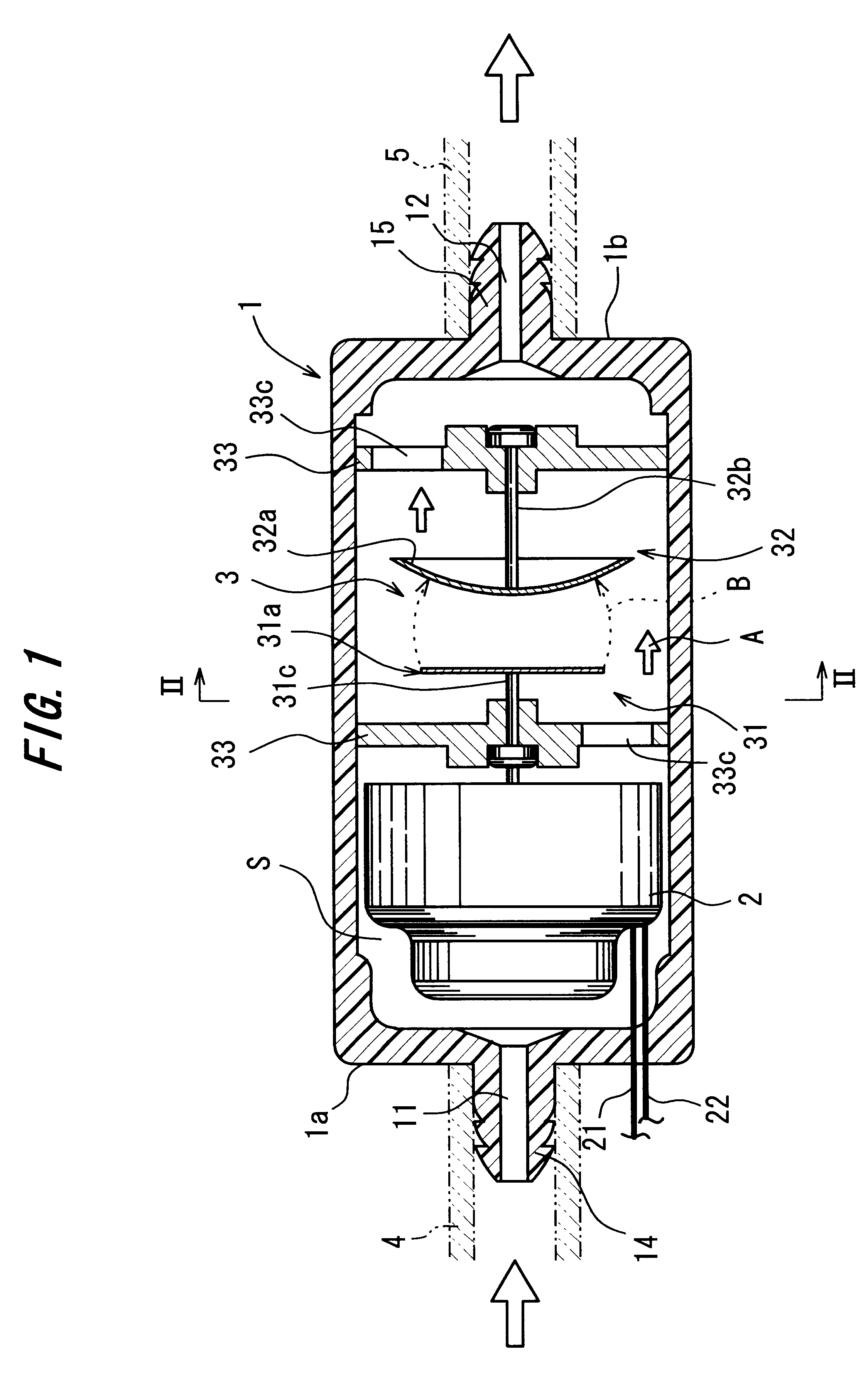
FIG. 1 is a sectional view showing an ion generator according to the invention, whereas FIG. 2 is an enlarged sectional view thereof taken on the line II--II in FIG. 1.

The ion generator is designed to ionize air for supplying the ionized air to an intake manifold interposed between an air cleaner and a cylinder within an internal combustion engine.

In the ion generator, a cylindrical casing 1 is formed with an intake port 11 at one end 1a thereof and with an exhaust port 12 at the other end 1b thereof. A space between the intake port 11 and the exhaust port 12 defines an air-flow passage A. A high-voltage generator 2 is disposed on an upstream side of the air-flow passage A, whereas an ionization electrode 3 is disposed on a downstream side thereof.

The casing 1 is formed from a synthetic resin, such as polyetherimde, having a connection port 14 for an intake pipe 4 protruded from one end 1a thereof and a connection port 15 for an exhaust pipe 5 protruded from the other end 1b thereof...

second embodiment

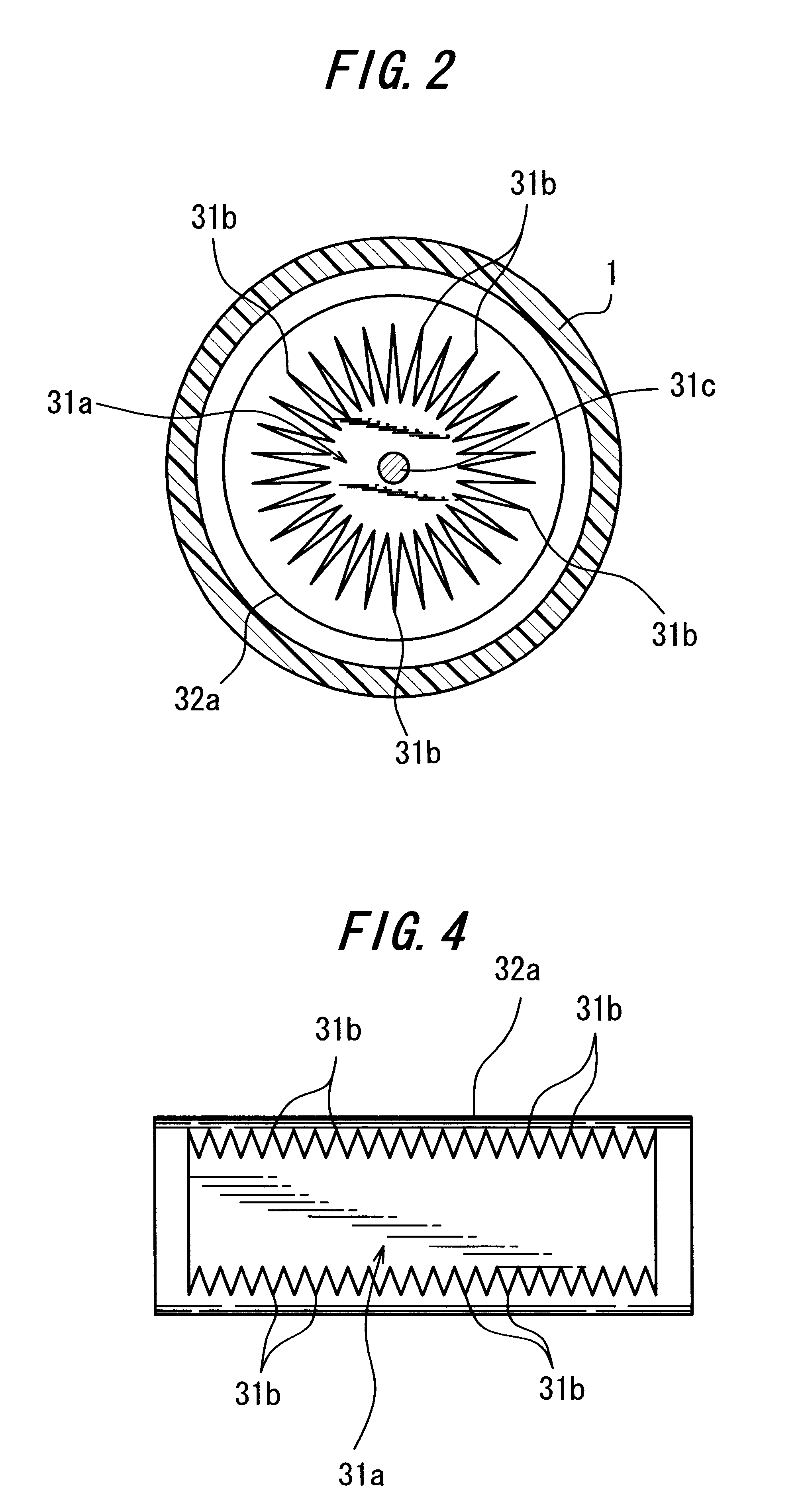
In the second embodiment, the positive pole 31a is formed with a large number of pointed ends 31b on the opposite ends thereof so that a large quantity of corona discharge B develop from the pointed ends 31b along the parallel longitudinal lines with respect to the positive pole 31a. This provides for an efficient air ionization and the reduction of the current value of the primary winding of the transformer to about 1 / 3 of that of the prior-art arrangement.

FIG. 6 is a sectional view showing an ionization electrode 3 according to a third embodiment of the invention. In this ionization electrode 3, a negative pole 32a is in the form of a cylinder whereas a plural number of rectangular positive poles 31a (four poles are shown in the figure) are arranged peripherally of the negative pole 32a as presenting their respective flat surfaces to a peripheral surface of the negative pole 32a, the positive pole 31a formed with the sawtooth-like pointed ends 31b on its opposite side edges as sho...

fourth embodiment

FIG. 7 is a sectional view showing an ionization electrode 3 according to the invention. The ionization electrode 3 includes two sets of one rectangular positive pole 31a formed with the sawtooth-like pointed ends 31b on its opposite side edges as shown in FIG. 4, and a pair of cylindrical negative poles 32a, each of which is disposed in correspondence to each of the side edges of the positive pole and has a generatrix thereof extended in parallel with the corresponding pointed ends 31b. The two sets of the positive pole and negative poles are arranged in a vertically symmetrical fashion. The pair of positive poles 31a sandwich an iron plate 34 therebetween.

Similarly to the ionization electrode of FIG. 6, this ionization electrode 3 is also capable of generating a large quantity of corona discharge B in a stable manner.


PUM


Abstract

An ionization electrode consists of a plate-like positive pole (31a) formed with plural pointed ends (31b) on its outer edge, and a spheric negative pole (32a) opposing a flat surface of the positive pole (31a). Since the pointed ends (31b) of the positive pole (31a) are not in direct face-to-face relation with the negative pole (32a), corona discharge is prevented from concentrating on some of the pointed ends (31b) that are closer to the negative pole (32b) than the rest due to the working errors or mounting errors of the poles. Therefore, the corona discharge occurs in a stable manner.

Description

The present invention relates to an ion generator adapted to generate ozone by ionizing air introduced into a casing.DESCRIPTION OF THE PRIOR ARTThere have been used ion generators designed to supply ionized air to intake manifolds of internal combustion engines for the purposes of enhancing the combustion efficiency thereof, improving the fuel economy and reducing the air pollution.FIG. 10 is a sectional view showing an exemplary prior-art ion generator. A casing 80 of this ion generator includes a cylinder body 89 which is formed from stainless steel or the like and the opposite ends of which are closed by caps 84, 85. One 84 of the caps is formed with an intake port 86 whereas the other cap 85 is formed with an exhaust port 87. The ion generator has an arrangement wherein a gap between the intake port 86 and the exhaust port 87 defines an air-flow passage A in which a high-voltage generator 88 is disposed on an upstream side and an ionization electrode I is disposed on a downstre...

Claims


Application Information

Patent Timeline
IPC IPC(8): H01J27/02A61L2/20A61L9/015A61L9/22B03C3/155B03C3/40F02M27/04H01T19/00H01T19/04H01T23/00
CPCA61L9/015A61L9/22F02M27/04H01J27/02A61L2/202F23K2300/101H01T19/00H01T23/00
Inventor MOTOUCHI, KAZUO
Owner MOTOUCHI KAZUO
Why Eureka
Try Eureka