Rotary vane pump with vane wear access port and method

a technology of wear access and vane, which is applied in the direction of rotary/oscillating piston pump components, machines/engines, liquid fuel engines, etc., can solve the problems of composite carbon parts that are similar in wear, chipping and fracture, and the nature of the vane lubrication technique is destructive to the pump

Inactive Publication Date: 2004-08-03
TIMOTHY H HENDERSON
View PDF18 Cites 5 Cited by
  • Summary
  • Abstract
  • Description
  • Claims
  • Application Information

AI Technical Summary

Benefits of technology

to provide an improved method of determining the remaining useful life of a rotary vane pump without having to disassemble the pump to make that determination.
As is shown in FIGS. 12-13, the sidewall of the stator 61 is provided with an access port 70 that communicates with the chamber of the stator 61. As shown in FIG. 12, progressive wear of the vanes 66 can be determined by means of a probe 75. The probe 75 may optionally include a sleeve 76 having an enlarged flange 78 on one end through which is positioned an elongate stylus 79. The exterior side wall of the stator 61 is provided with a flattened area 80 normal to the extended axis of a slot 65A-F when properly aligned with the access port 70, as shown in FIG. 12. By placing the sleeve 76 against the flattened area 80, proper alignment and thus proper insertion of the stylus 79 into the slot 65C is attained.

Problems solved by technology

Although providing improved performance over the prior carbon parts, similar wear, chipping and fracture problem exist with composite carbon parts.
While these lubricating methods work well for dry pump applications, the nature of the vane lubrication technique is destructive to the pump.
The deposited graphite film is itself worn away by continued operation of the pump, and is eventually exhausted out of the pump.
Therefore, the vanes wear and lose length as the pump operates.
At some point in time, the length of the vanes will become so short that they will not slide properly in the slot, which may lead to pump failure.
Failure of a dry air pump can render one or more aircraft systems inoperative.
In addition, most pump failures occur in flight.
Dry air pump performance is generally unaffected by wear on the vanes until total failure.
Moreover, pump efficiency does not typically degrade enough to be noticed by the pilot until total failure.
However, this generally does not occur until near complete failure of the pump.
The inventor has determined that the incidence of structural failure of the vane / rotor combination begins to increase appreciably after the vanes wear to a certain length.
The incidence of failures continues to increase and the rate of failure per unit time increases dramatically as the vanes continue to wear shorter.
By the time remaining vane length reaches about 64% of the original length, about 50% of installed pumps have failed, and more than 90% of those failures can be traced to malfunctions relating to vane length.
When the remaining vane length falls below 64% of the original length, more than 98% of the installed pumps studied have failed, and 95% of those failures are related to vane length.
Roughness of the interior surfaces can occur through many different causes, such as elevated temperatures and pressures, dirty filters, etc.
Regardless if the vane wear is normal, or abnormally accelerated, when the vane length reaches a certain percentage of the original length, the likelihood of pump failure increases significantly.
The current state of the art relating to dry air pump performance and efficiency does not adequately address how to determine when the vanes of the pump have reached a point requiring pump replacement or repair.
Presently, there is no effective and simple way to inspect the state or rate of wear of the vanes in this type of pump.
There is also no simple and cost effective way to determine the remaining useful life of a dry air pump.
This is neither cost effective nor efficient since the pump may have a significant amount of usage time still available, or, if wear was abnormally fast, would not be done in time.
Thus, the opportunity arises to remove from service pumps likely to fail.

Method used


Image

  • Rotary vane pump with vane wear access port and method
  • Rotary vane pump with vane wear access port and method
  • Rotary vane pump with vane wear access port and method

Examples


Embodiment Construction

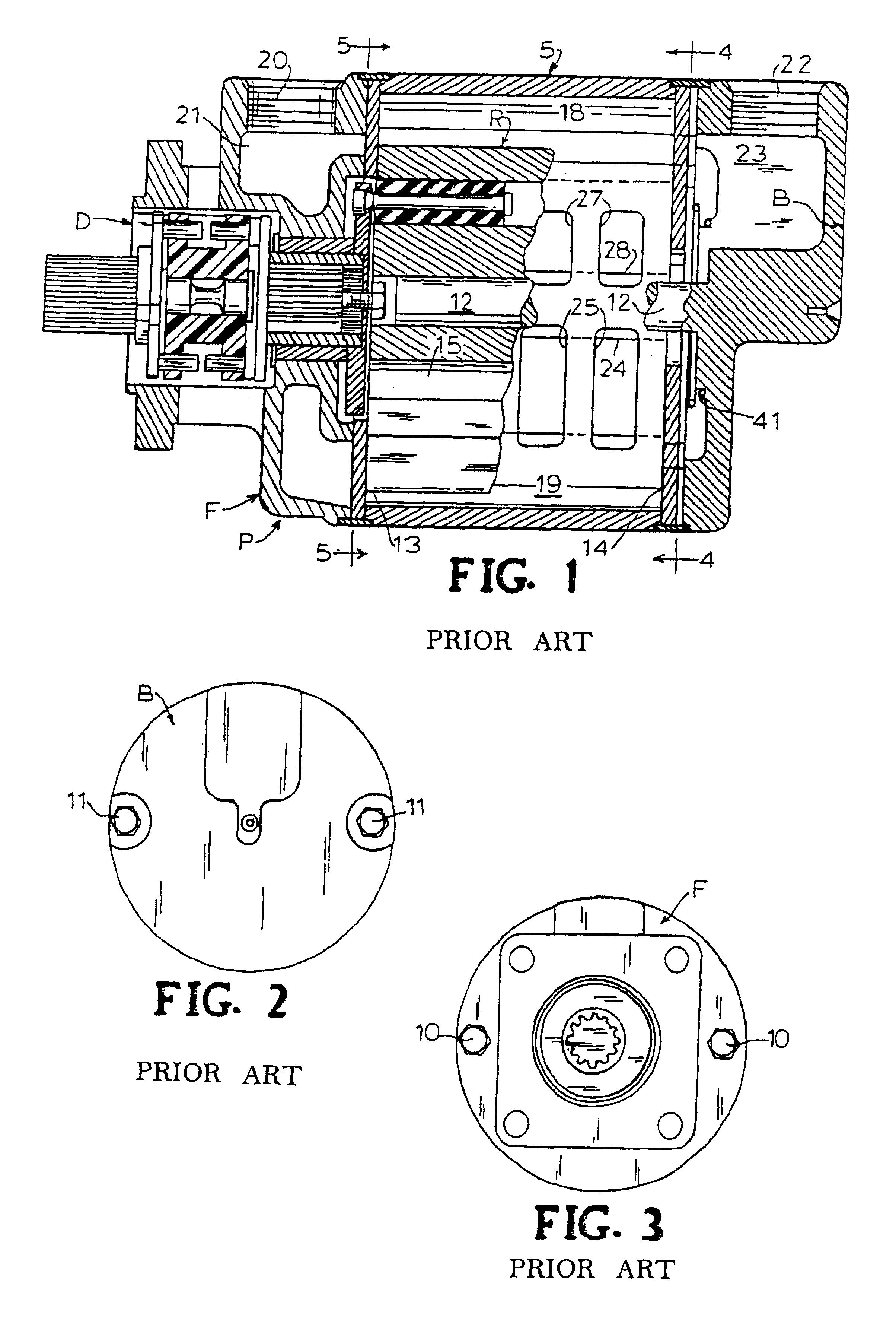
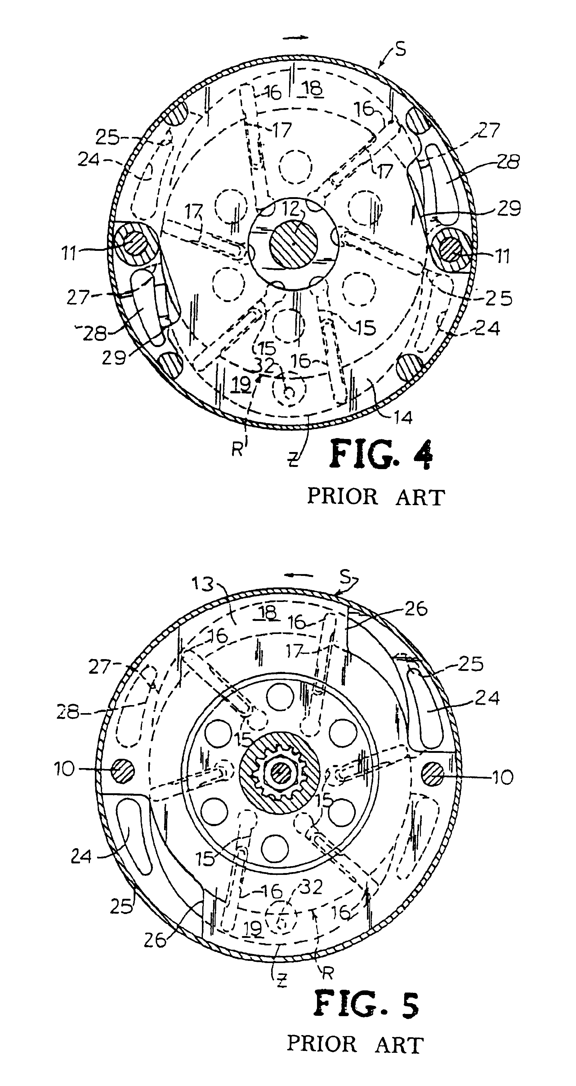
Referring now specifically to the drawings, a known vane pump is illustrated in FIGS. 1-5. As illustrated in FIG. 1, the rotary vane-type pump P has a central annular body or stator S, a rotor R, a front flange F secured to an inlet end of stator S, a back flange B secured to the outlet end of stator S, and a drive assembly D mounted on the front flange F for driving rotor R.

Front flange F and back flange B can secured to stator S by any known type of securing device as long as the pump parts S, F, and B are securely held in place during operation. FIGS. 2 and 3 illustrate the back flange B and front flange F being secured to stator S by two sets of screws 10 and 11, respectively. Each set of screws 10 and 11 are diametrically opposed on back flange B and front flange F. Preferably, back flange B and front flange F are mounted to stator S such that screws 10 are coaxially aligned with screws 11. Back flange B is provided with a central stud 12 which extends into and at least partial...


PUM


Abstract

A rotary vane pump, including a housing within which is rotatably mounted a rotor having a plurality of slots therein with a vane positioned for sliding movement within each of the slots. An access port is formed in the housing communicating with the rotor at a reference position in relation to the slots. The access port is sized to permit alignment of any one of the slots with the access port by rotating the rotor, maintaining the vane within the aligned one slot and at a datum within the slot, and permitting entry into the access port of an aligned slot of a stylus having a predetermined length in relation to the datum for determining the length of the vane. A determination of whether wear to the vane has met or exceeded a predetermined amount can be determined by reference to a portion of the stylus exterior to the access port.

Description

TECHNICAL FIELD AND BACKGROUND OF THE INVENTIONThe present invention relates to rotary vane pumps having self-lubricating sliding vanes. More particularly, the present invention is directed to a method and apparatus for inspecting the sliding vanes in a rotary vane pump to determine the amount of wear to the vanes without having to disassemble the pump housing.Sliding rotary vane pumps have been used for several years for a multitude of mechanical and industrial applications and can be exposed to a wide range of environmental conditions. These pumps can be used in both gas and liquid pumping applications. One type of sliding rotary vane pump is a dry air pump. In the general aviation field prior to the early 1960's, the vacuum systems which powered gyros were driven by pumps which were lubricated by oil and referred to in the art as wet pumps. In the 1960's, the oil lubricated, or wet vane vacuum pumps, were replaced by dry vacuum pumps constructed of carbon vanes and rotors which w...

Claims


Application Information

Patent Timeline
Patent Type & Authority Patents(United States)
IPC IPC(8): F01C21/10F01C21/00F01C21/08F04C15/00F04C2/00F04C2/344
CPCF01C21/0818F01C21/104F04C2/3446F04C15/00F04C15/0096F04C2270/16F04C2270/80
Inventor HENDERSON, TIMOTHY H.
Owner TIMOTHY H HENDERSON
Why Eureka
Try Eureka