Blasting method

Inactive Publication Date: 2004-08-03
LIVE OAK MINISTRIES
View PDF49 Cites 53 Cited by
  • Summary
  • Abstract
  • Description
  • Claims
  • Application Information

AI Technical Summary

Problems solved by technology

Although this method is more accurate than other prior art methods for determining rock burdens, the calculations performed by the FACE 3-D.RTM. software giv

Method used


Image

  • Blasting method
  • Blasting method
  • Blasting method

Examples


example 1

Prior Art

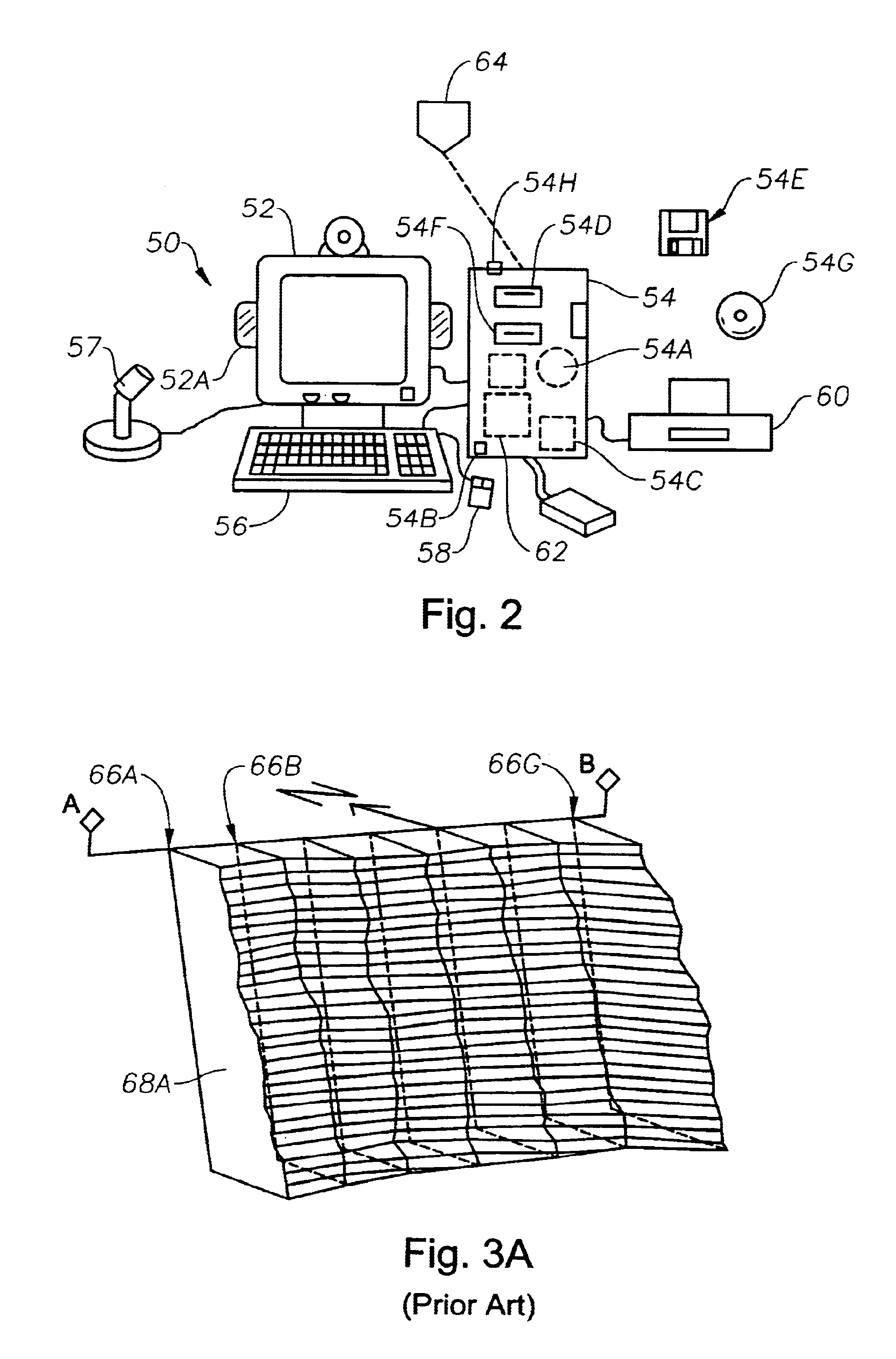
In a typical prior art procedure alluded to above, a rock face is surveyed using laser rangefinding equipment such as the commercially available QUARRYMAN.RTM. device. Next, rock face profiling software such as FACE 3-D.RTM. software available from Blast Design International, Inc. or a similar software program can be used to produce a three-dimensional model of the rock face, from which isometric, plan and cross-sectional views may be constructed. FIG. 3A shows the computer model of the rock face in front of a planned drill line A-B as generated by the FACE 3-D.RTM. software.

Once the rock face has been surveyed, the computer model generated by the software may be used to evaluate borehole positions, spacings, angles, and to calculate the explosive energy distribution throughout the rock mass on a hole-by-hole basis for specified explosives. In a particular example, a drill line A-B indicated in FIG. 3A and a series of seven boreholes 66a, 66b, . . . 66g along the drill line...

example 2a

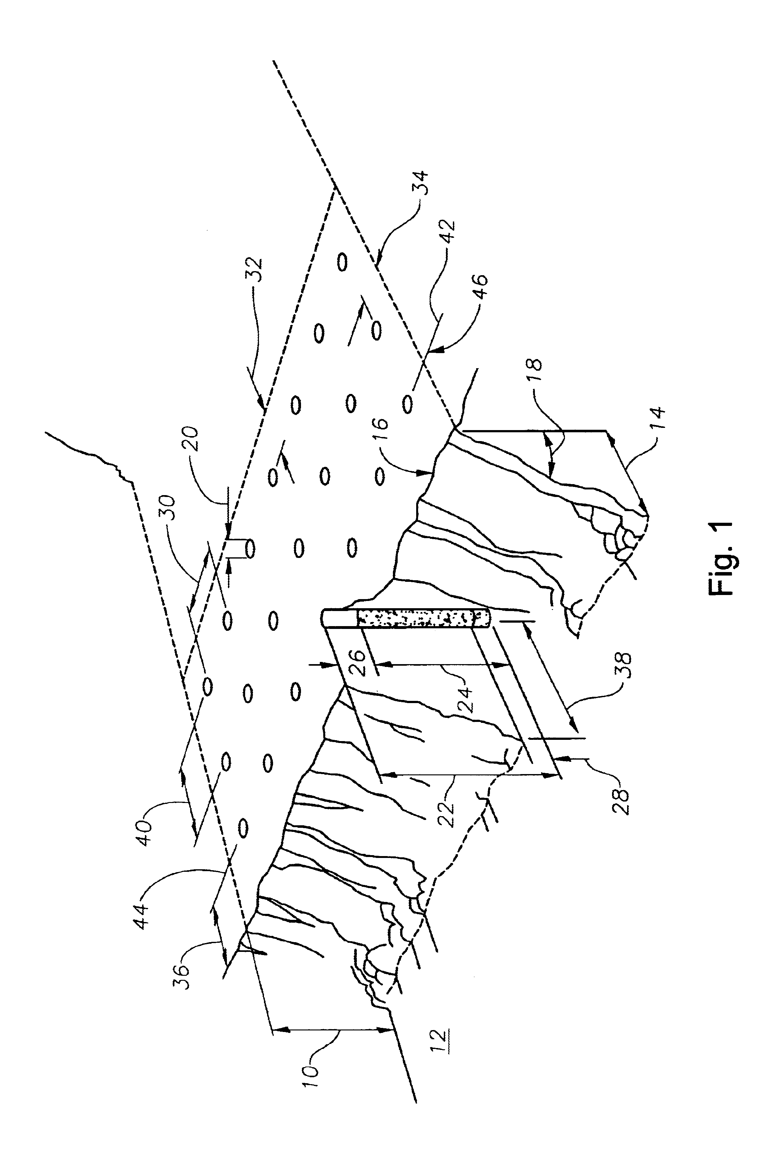
One example of a procedure in accordance with the present invention may be based on the following blasting site characteristics:

Face Height (FH) at start point=80 feet

Desired Stem Height (SH)=10 feet

Subdrilling (SD)=5 feet

Bore Hole diameter (d)=6.5 inches (16.5 centimeters (cm))

Explosive=ANFO

(Density (ANFO) (.rho..sub.EXP)=0.82 g / cm.sup.3 ; Specific Energy (ANFO)=880 cal / g)

Desired MF=3 tons rock per pound ANFO

Rock density (.rho..sub.R)=2.25 tons / yd.sup.3

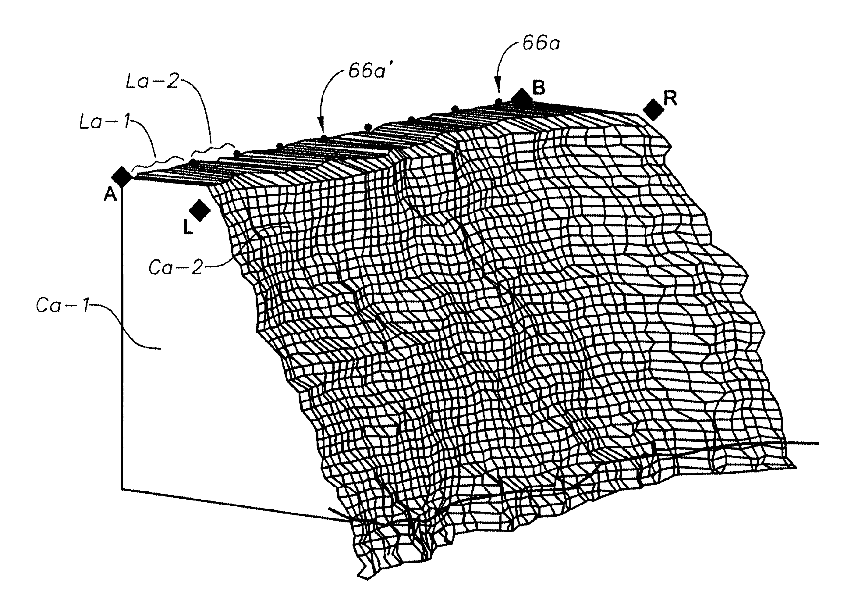
The optimum positions for boreholes along a selected drill line to achieve proper fragmentation are determined as follows, with reference to FIG. 3B, which represents a portion of the same bench shown in FIG. 3A.

1. The bench, including the rock face, is electronically surveyed and modeled, preferably with optional discount for the presence of residual debris ("muck") that may have been interpreted as solid rock. When modeling is done by digital surveying methods, e.g., by use of the QUARRYMAN.RTM. system, the muck can be discounted f...

example 2b

An alternative procedure, described herein with reference to FIG. 3B, follows the steps of Example 2A except that instead of steps 7, 8 and 9 of Example 2A, the following steps 7', 8' and 9' are preferred:

7'. The length of the hypothetical borehole and the hypothetical volume of explosive therein are revised based on the average of the heights of the defined cross sections, and the target rock burden B.sub.T is recalculated, based on the revised hypothetical borehole height and desired MF.

8'. The mass of rock in the layer is added to all previously defined layers defined from the start point (if any) and the accumulated rock mass is compared to the target rock burden.

9'. If the accumulated rock mass is less than the revised B.sub.T, another cross section and layer are defined and steps 6, 7' and 8' are repeated. In this way, the length and volume of the hypothetical borehole and the associated target rock burden are up-dated on an iterative basis based on the average heights of all ...


PUM


Abstract

Methods for evaluating drill pattern parameters such as burden, spacing, borehole diameter, etc., at a blast site are disclosed. One method involves accumulating the burden contributed by successive layers of rock and matching the accumulated rock burden to a target value for a borehole having a length related to the average height of the layers. Another method relates to varying drill pattern parameters and characteristics to match blast design constraints, including the substitution of one explosive material for another by the proper balance of materials and/or output energies to the associated rock burden. Analysis of deviations from target rock burdens and corrective measures are disclosed, as well as cost optimization methods. The various methods can be practiced using an appropriately programmed general purpose computer.

Description

1. Field of the InventionThis invention pertains to bench blasting methods and, in particular, to a method of selecting the placement of boreholes along a drill line.In modern bench blasting, vertical or near vertical holes are drilled adjacent to a rock face and are loaded with explosive charges that are then detonated. The detonation fractures the rock mass between the borehole and the rock face and displaces the resulting fractured rock. The resulting broken rock, known as "muck", is removed and a new free rock face is thus exposed. If the muck contains a desired product, it can be gathered and processed. Otherwise, it may simply be removed from the blasting site to permit further blasting or other activities.2. Related ArtU.S. Pat. No. 3,377,909 to Grant et al, issued Apr. 16, 1968, discloses the use of a "powder factor" (cubic yards of earth per pound of explosive) to characterize a borehole pattern in a coal field strip mine and discloses a "normal" spacing for ANFO (see col. ...

Claims


Application Information

Patent Timeline
IPC IPC(8): E21C41/00E21C41/26F42D1/00F42D3/00F42D3/04F42D1/08G06G7/48G06G7/00E21C37/16
CPCE21C37/16F42D1/00G01V9/00G06F17/60
Inventor HECK, SR., JAY HOWARD
Owner LIVE OAK MINISTRIES
Why Eureka
Try Eureka