Automatically tracking scanning sonar

a scanning sonar and automatic tracking technology, applied in the field of ultrasonic transmitreceiver apparatuses, can solve the problems producing false images on-screen, and increasing hardware scale, and achieves the effects of increasing hardware or manufacturing cost scale, large grating lobes and side lobes, and high angular resolution

Inactive Publication Date: 2004-08-17
FURUNO ELECTRIC CO LTD
View PDF6 Cites 32 Cited by
  • Summary
  • Abstract
  • Description
  • Claims
  • Application Information

AI Technical Summary

Benefits of technology

to provide an ultrasonic transmit-receive apparatus and a scanning sonar employing the ultrasonic transmit-receive apparatus which can solve the aforementioned false image problem and offer a higher angular resolution without causing an increase in the scale of hardware or in manufacturing cost even if a transducer is so structured to produce relatively large grating lobes and side lobes.

Problems solved by technology

Due to this structure, the conventional transducer produces grating lobes and receives reflections from other directions than an intended sounding direction, eventually producing false images on-screen as a consequence.
Although this approach is effective to some extent, an increase in the number of transducer elements leads to an increase in the number of such circuits as drive circuits for driving the individual transducer elements, control circuits for controlling the drive circuits, receive circuits and signal processing circuits for processing received signals, eventually causing an increase in the scale of hardware and a considerable cost increase.

Method used


Image

  • Automatically tracking scanning sonar
  • Automatically tracking scanning sonar
  • Automatically tracking scanning sonar

Examples


Embodiment Construction

The invention is now described in detail referring to the appended drawings.

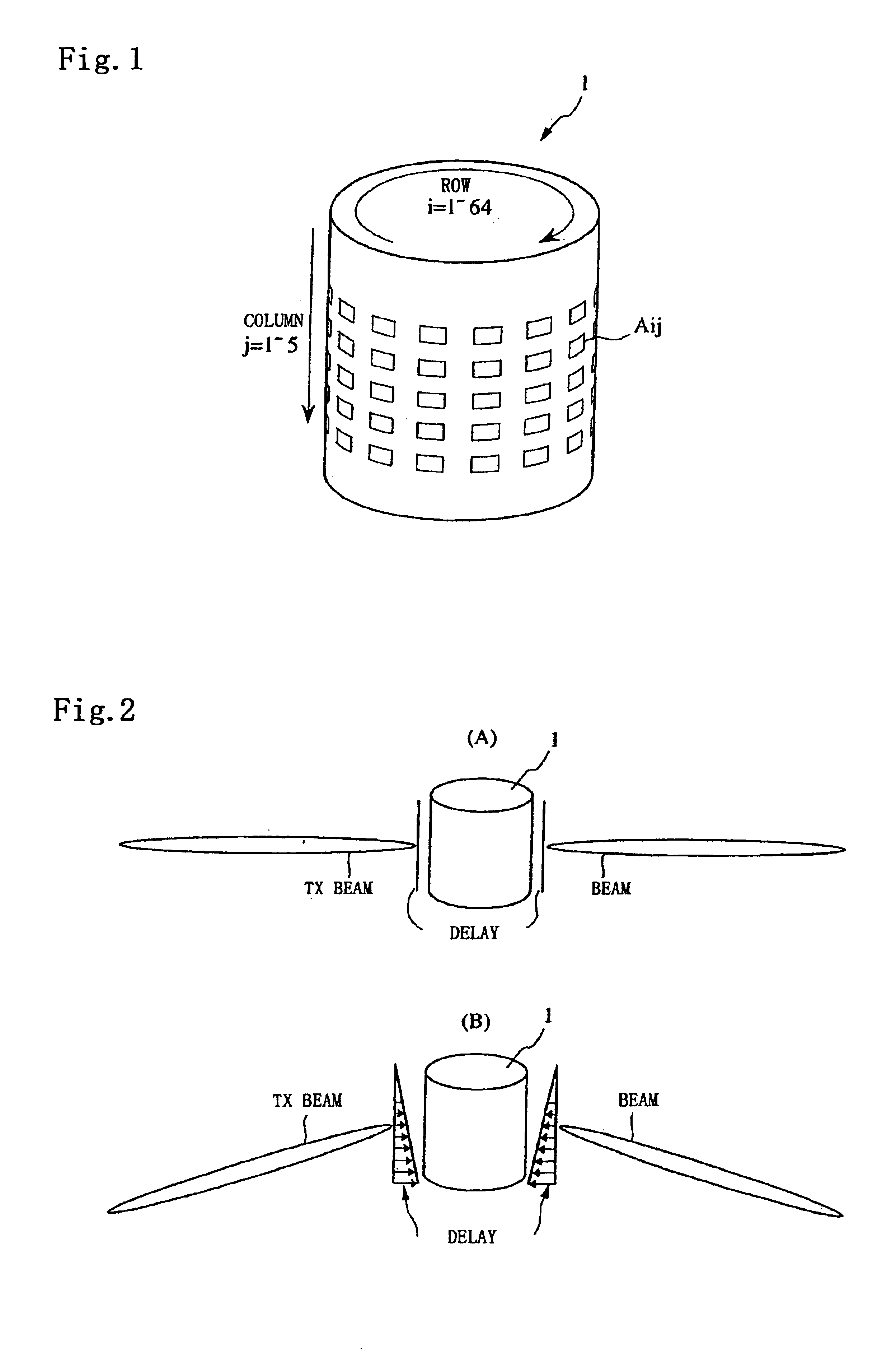
FIG. 1 is a perspective view showing the construction of a cylinder-shaped transducer 1 used in a scanning sonar according to a preferred embodiment of the invention. As depicted in FIG. 1, the transducer 1 includes 320 transducer elements Aij (i=1 to 64, j=1 to 5) arranged in rows and columns. More specifically, the transducer elements Aij are arranged on a cylindrical outer surface of the transducer 1 in 5 rows by 64 columns. The transducer 1 is mounted on the bottom of a vessel in such a manner that the central axis of the transducer 1 is vertically positioned.

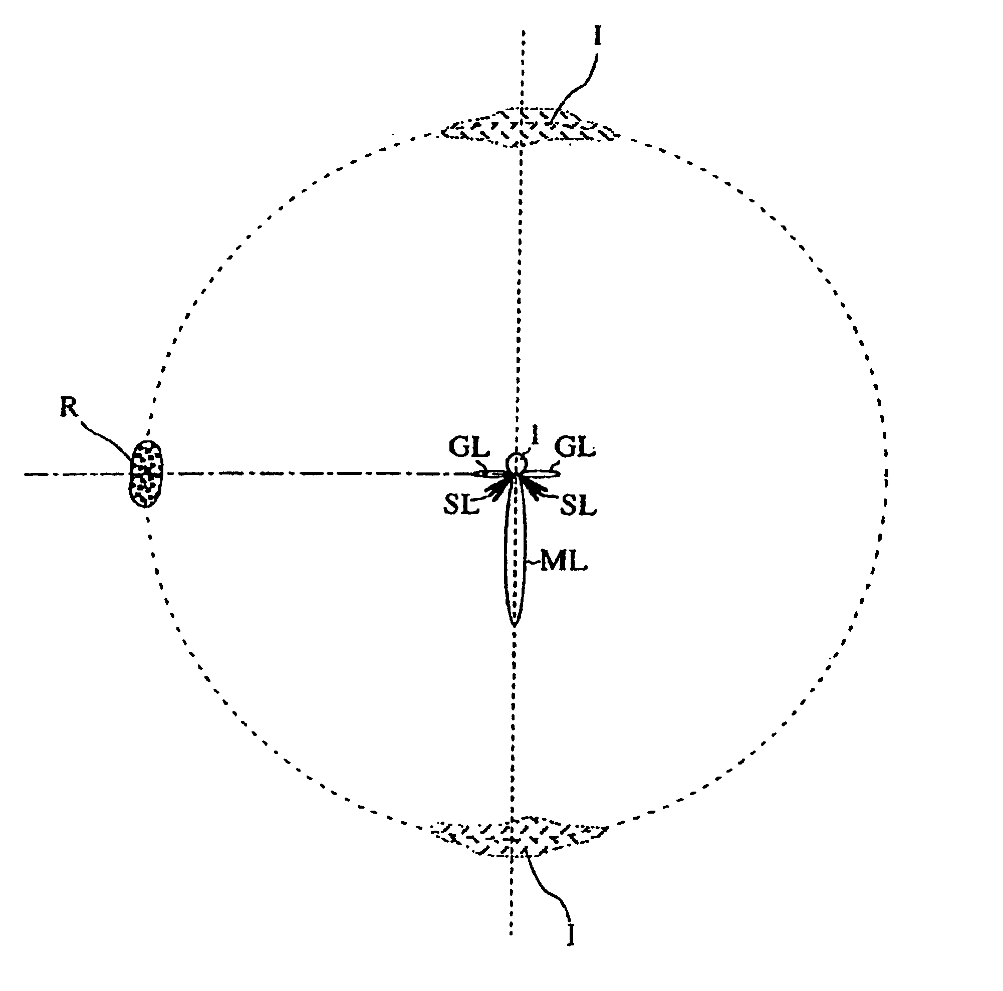
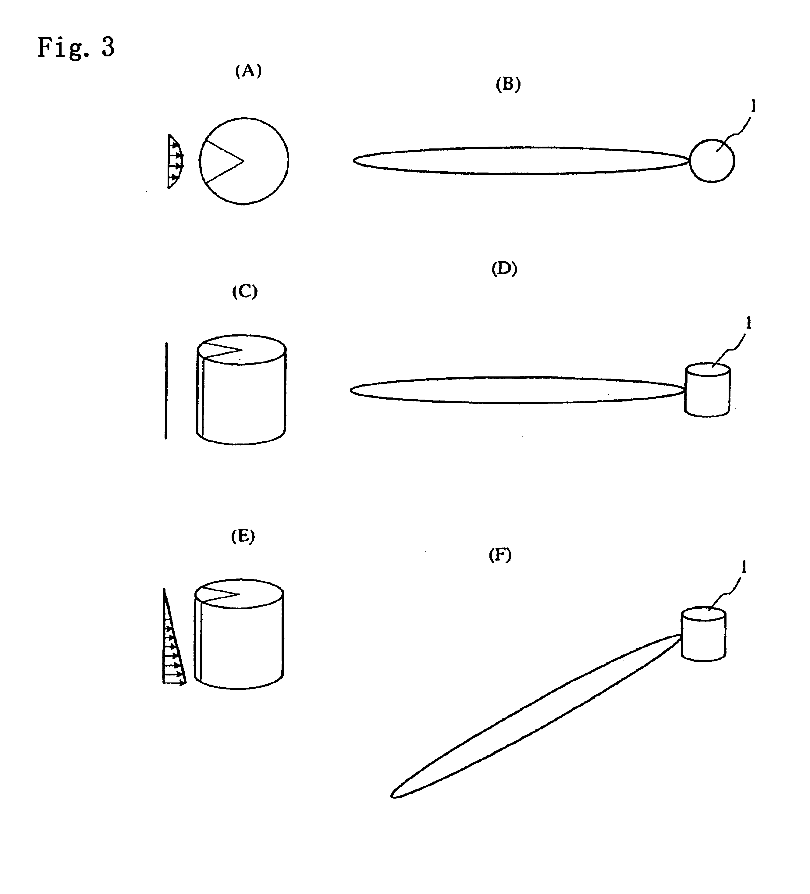
FIGS. 2A and 2B are diagrams showing how an ultrasonic transmitting beam is produced, in which FIG. 2A particularly shows directivity of the transmitting beam as it is formed when sounding all directions around the vessel in a horizontal plane (tilt angle=0.degree.), and FIG. 2B particularly shows how the transmitting beam is formed when sounding al...


PUM


Abstract

The invention provides an ultrasonic transmit-receive apparatus which solves a false image problem caused by grating lobes and side lobes and offers high bearing resolution without increasing in the scale of hardware or in manufacturing cost. Using a transducer having multiple transducer elements arranged on a surface of the transducer along its circumferential direction, the apparatus emits ultrasonic waves in directionally varying frequency bands and receives echo signals from specified angular directions while selecting the frequency from one direction to another. In a Doppler transmission method, for example, the apparatus drives the individual transducer elements in such a manner that the ultrasonic waves emitted by the transducer elements are equivalent to ultrasonic waves emitted from an imaginary moving sound source moving within a circle enclosed by the multiple transducer elements arranged along the circumferential direction, so that the transducer elements emit ultrasonic signals at directionally varying Doppler shift frequencies.

Description

1. Field of the InventionThis invention relates to an ultrasonic transmit-receive apparatus for detecting underwater objects, for instance, by transmitting and receiving ultrasonic waves as well as to a scanning sonar employing the ultrasonic transmit-receive apparatus.2. Description of the Prior ArtConventionally, scanning sonars are used for detecting underwater targets. Typically, a scanning sonar is provided with a generally cylinder-shaped transducer like the one shown in FIG. 1 for detecting underwater targets around a vessel on which the scanning sonar is installed. The scanning sonar produces an ultrasonic transmitting beam directed in all directions around the transducer by causing its transducer elements to oscillate. Referring to FIG. 1, the individual transducer elements of the transducer are driven by signals which are precisely phase-controlled to introduce appropriate time delays in driving the transducer elements of one ringlike horizontal array (or row) to another, ...

Claims


Application Information

Patent Timeline
Patent Type & Authority Patents(United States)
IPC IPC(8): B06B1/06G01S15/00G01S15/42G01S7/52G01S15/89G01S15/87G01S15/06G01S7/523G01S7/62
CPCB06B1/0633G01S7/52003G01S15/42G01S15/87G01S15/89G01S7/52004G01S15/86
Inventor NISHIMORI, YASUSHIWATANABE, KEN'ICH
Owner FURUNO ELECTRIC CO LTD
Why Eureka
Try Eureka