
Measurement of torsional dynamics of rotating shafts using magnetostrictive sensors

a magnetostrictive sensor and torsional dynamics technology, applied in the direction of work measurement, measurement devices, instruments, etc., can solve the problems of not only difficult use but costly implementation of methods, available methods generally lack long-term durability, and none of these efforts, however, disclose or anticipate detectors

Inactive Publication Date: 2004-08-24
SOUTHWEST RES INST
View PDF16 Cites 28 Cited by
  • Summary
  • Abstract
  • Description
  • Claims
  • Application Information

AI Technical Summary

Benefits of technology

The present invention relates to methods and devices for non-contact monitoring and measurement of torque in rotating shafts using magnetostrictive sensors. The technical effects of this invention include the ability to measure torque without physical contact with the rotating shaft and the use of a detector that does not require some form of periodic external excitation of the magnetostrictive material. The invention offers a more efficient means for monitoring and controlling machinery dynamics, improving operational conditions, and reducing wear on the machinery components. The prior art methods, such as shaft encoders and torsional accelerometers, are difficult to use and costly. The present invention provides a non-contact means for measuring torque that is reliable and durable for long-term monitoring and control of machinery.

Problems solved by technology

In many situations, these methods are not only difficult to use but costly to implement.
In addition, the available methods generally lack long-term durability, which is essential for on-line monitoring and control during the service life of high speed rotational machinery.
None of these efforts, however, disclose or anticipate a detector that does not include some form of periodic external excitation of the magnetostrictive material.

Method used


Image

  • Measurement of torsional dynamics of rotating shafts using magnetostrictive sensors
  • Measurement of torsional dynamics of rotating shafts using magnetostrictive sensors
  • Measurement of torsional dynamics of rotating shafts using magnetostrictive sensors

Examples


Embodiment Construction

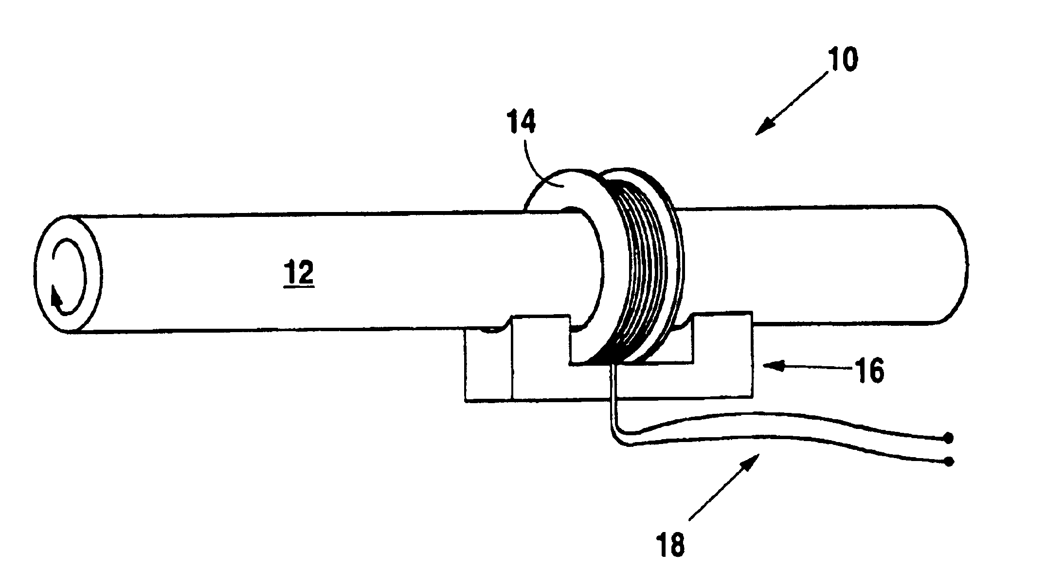
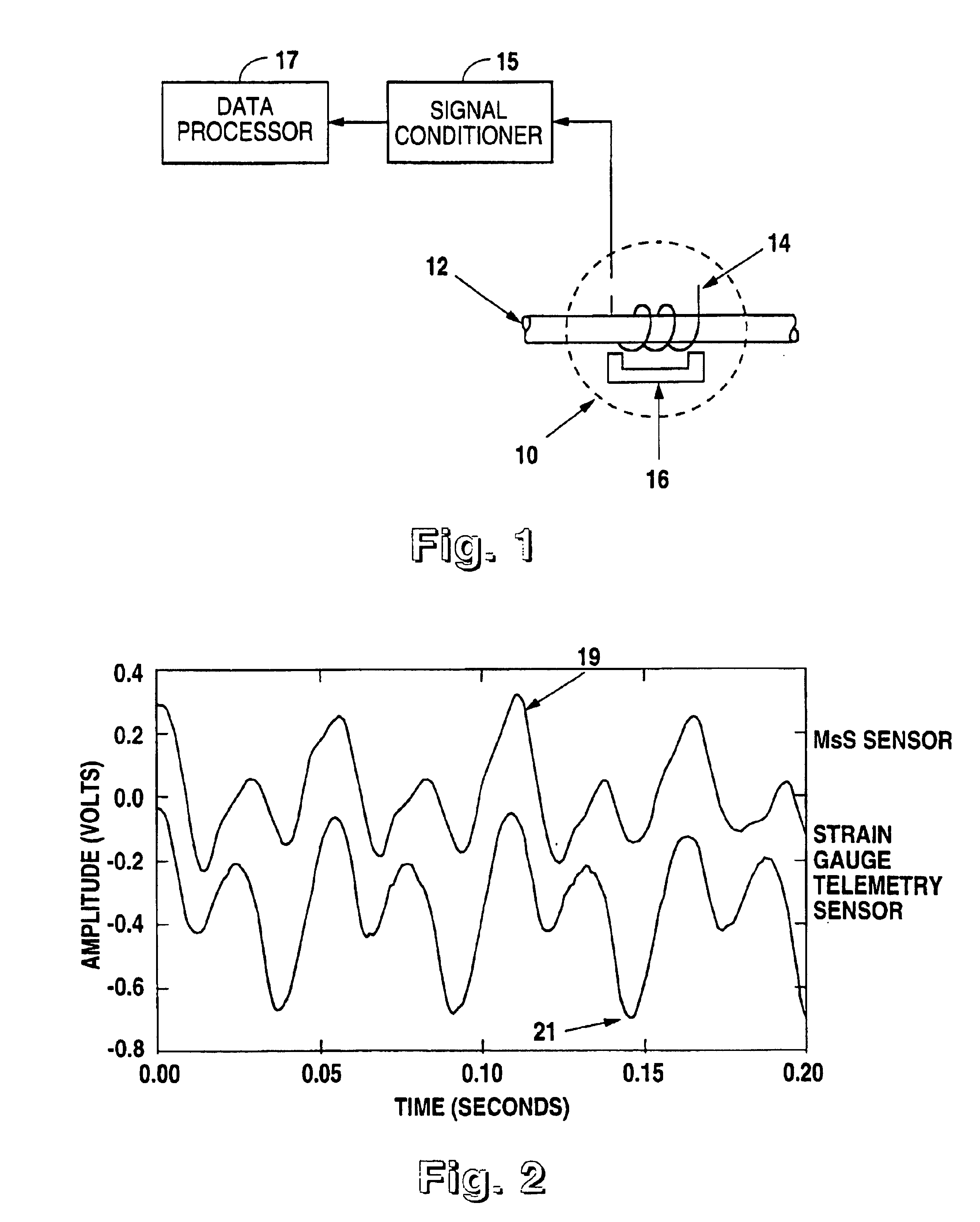
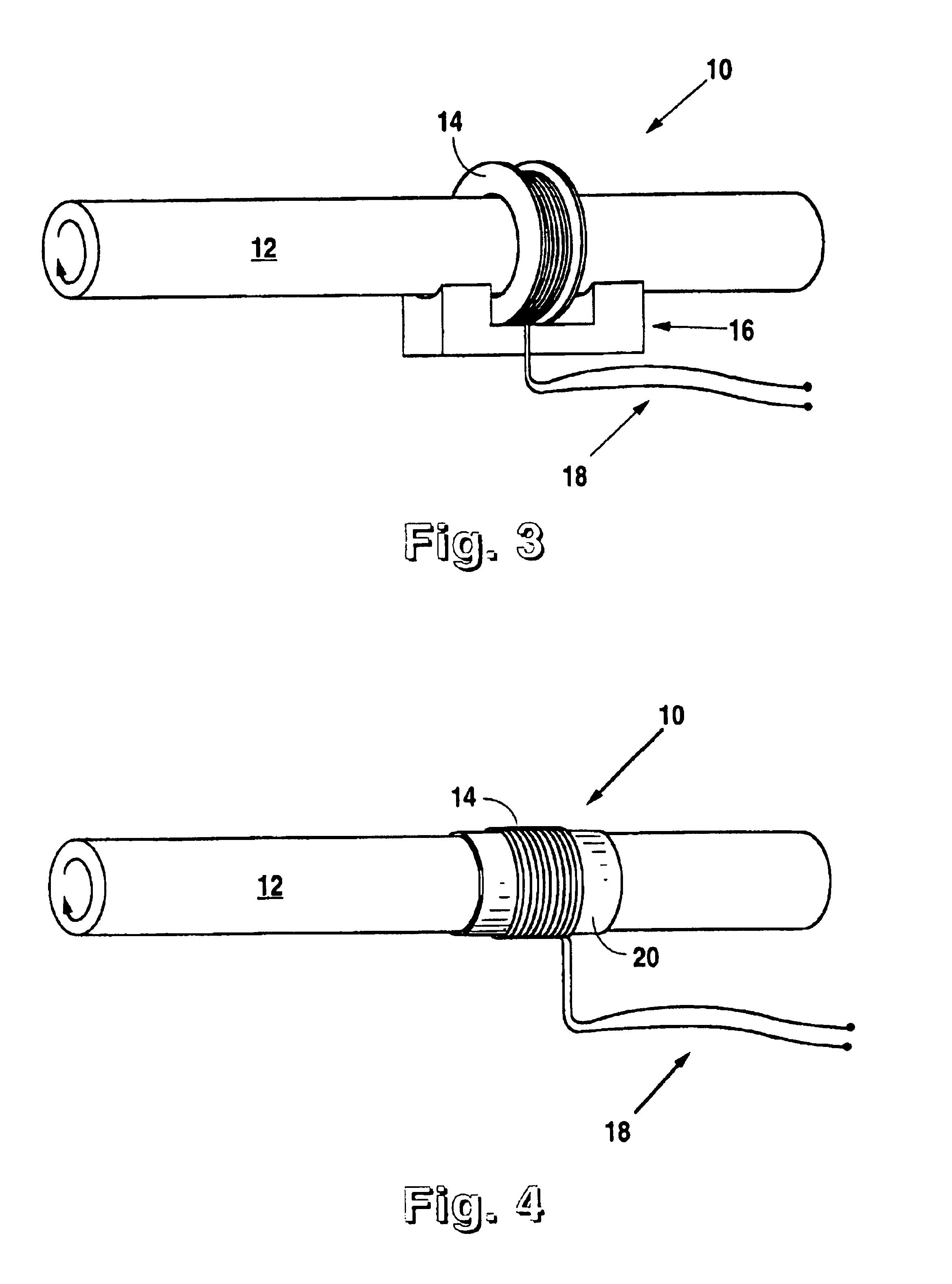
In the present invention, measurements of the torsional dynamics of a rotating shaft are accomplished without making physical contact with the shaft through the use of a magnetostrictive sensor (MsS). FIG. 1 illustrates the basic configuration of a MsS together with the accompanying electronics for signal conditioning. Since the MsS relies on a physical phenomenon known as the Villari effect (which refers to magnetic induction changes resulting from mechanical stress) peculiar to the ferromagnetic materials, the invented method is applicable to shafts made of ferromagnetic materials. If the shaft is not made of ferromagnetic materials, the invented method is still applicable by plating the shaft with a suitable ferromagnetic material such as nickel. In this case, the plating is necessary only in the local area on which the MsS is placed.

Signal detector (14) in FIG. 1 is a magnetic field sensing device, typically an inductive pickup coil, which either encircles or is placed adjacent ...


PUM

PropertyMeasurementUnit
diameteraaaaaaaaaa
diameteraaaaaaaaaa
diameteraaaaaaaaaa

Abstract

A device and method for the non-contact measurement of dynamic torsion in a rotating shaft using magnetostrictive sensors (MsS). The monitoring and detection system has specially configured magnetostrictive signal detectors that include inductive pick-up coils, in which signals corresponding to localized shaft torques are induced. The basic system sensor utilizes either a permanent DC bias magnet positioned adjacent the rotating shaft or applies a residual magnetic field to the shaft. The techniques described in conjunction with the system are particularly advantageous for on-line monitoring of loaded rotating shafts that are integral parts of power trains, by providing a low-cost and a long-term sensor for acquiring dynamic data of the shaft portion of the machinery system being monitored and / or controlled.

Description

I. Field of the InventionThe present invention relates generally to methods and devices for the noncontact monitoring and measurement of the torsional dynamics of rotating shafts. The present invention relates more specifically to methods and devices for the noncontact monitoring and measurement of stationary and transient torques in rotating shafts using magnetostrictive sensors (MsS).II. Description of the Prior ArtIt is common in many different machine systems, for mechanical power from an electrical motor, combustion engine, or gas turbine to be transmitted to a load through a power train of some type. Rotating shafts are frequently integral parts of such power trains. A variety of machinery dynamics, including vibration, lateral movement, and torsional motion, have a direct effect on the operational conditions of these machine systems. The monitoring of these machinery dynamics offers, therefore, a valuable means of diagnosing and correcting machinery problems in a manner that ...

Claims


Application Information

Patent Timeline
Patent Type & Authority Patents(United States)
IPC IPC(8): G01L3/10
CPCG01L3/102G01L3/105
Inventor KWUN, HEGEONBURKHARDT, GARY L.TELLER, CECIL M.
Owner SOUTHWEST RES INST
Learn More