
Transfer of SS7 signalling message contents over packet broadcasting network (LAN) from multiple signalling points to single point (multiple point-to-point)

Inactive Publication Date: 2004-08-24
RPX CORP
View PDF8 Cites 3 Cited by
  • Summary
  • Abstract
  • Description
  • Claims
  • Application Information

AI Technical Summary

Benefits of technology

The methods and systems of the present invention thus efficiently and cost-effectively perform signal monitoring without the need for external devices to be connected to the system. By performing signal monitoring in accordance with the present invention, the computational costs for signal monitoring are reduced and the signal monitoring function is greatly streamlined. The inventive signal monitoring systems and methods also advantageously provide centralized signal monitoring since the signal monitoring for the entire network may be accomplished at a single network element if desired. Moreover, the inventive signal monitoring methods and systems allow signal monitoring to occur at any signaling point in the network and not just at a switch element thereof. Such results have not heretofore been achieved in the art.

Problems solved by technology

Needless to say, monitoring the messages received at the nodes to verify their accuracy and to ensure that they reach their intended location is a monumental task that must be constantly monitored or the telecommunication system runs the risk of performing poorly or shutting down altogether.
The problem associated with external protocol analyzers of this type is that they are required to be physically attached to nodes in the system.
Of course, this activity can be very time consuming, expensive and difficult when tracking faults and other events in the whole network.
Moreover, external protocol analyzers are expensive pieces of equipment that require constant servicing themselves in order to ensure that they perform and correctly yield useful and accurate signaling data for the switch.

Method used


Image

  • Transfer of SS7 signalling message contents over packet broadcasting network (LAN) from multiple signalling points to single point (multiple point-to-point)
  • Transfer of SS7 signalling message contents over packet broadcasting network (LAN) from multiple signalling points to single point (multiple point-to-point)
  • Transfer of SS7 signalling message contents over packet broadcasting network (LAN) from multiple signalling points to single point (multiple point-to-point)

Examples


Embodiment Construction

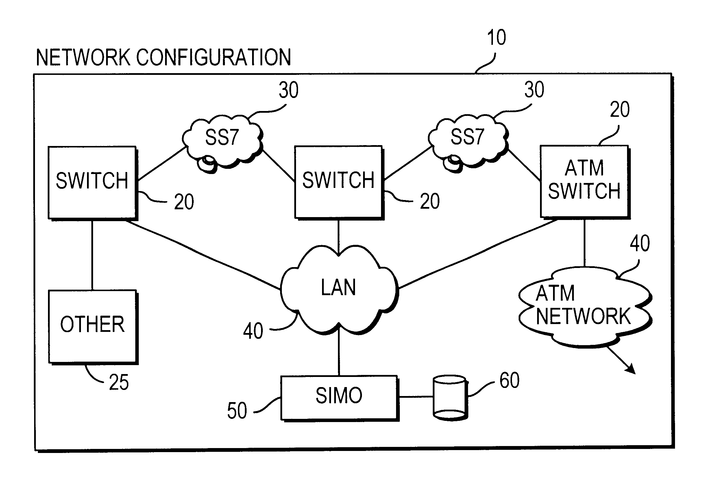
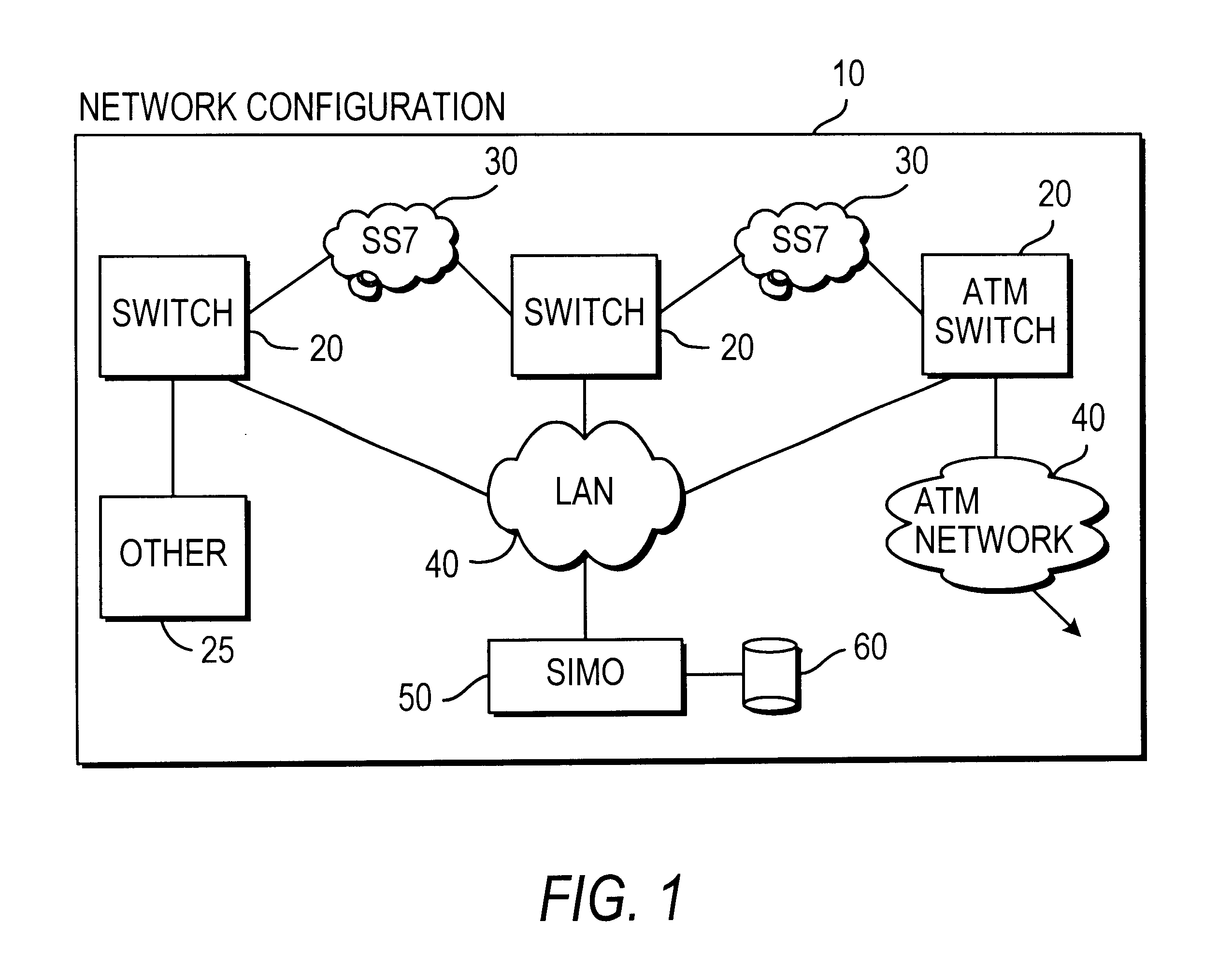
Referring now to the drawings, FIG. 1 depicts a network 10 having a plurality of network elements 20 in which signal monitoring in accordance with the present invention is practiced. The network elements 20 represent signaling points in the network from which signal monitoring in accordance with the present invention can be initiated. The network elements may comprise switches, computers, nodes or other devices known to those skilled in the art through which messages in the network will traverse. In a preferred embodiment, the network elements are switches, for example, the DX200 switch mentioned above, although it will be recognized by those with skill in the art that other switches and network elements may be equally capable of performing the inventive signal monitoring techniques disclosed herein. The invention is not intended to be limited to any particular network element, signaling point or switch. For convenience, the network elements or signaling points 20 will be referred t...


PUM


Abstract

Methods and apparatus for signal monitoring of messages in a telecommunications network having a plurality of switches and network elements therein alleviate the need for external hardware to be hooked up to nodes of the network to determine whether faults have occurred at the nodes. A signal monitoring application disclosed herein stores related message signals and messages in a relational database wherein messages and signals having common elements can be easily and quickly viewed. The SIMO application cross-references the messages and signals in the relational database according to a transaction table which categorizes and stores the messages according to parameters set out in the transaction table. This allows the messages to be ranked and viewed very quickly without the need to process them and expend valuable computational time and resources.

Description

1. Field of the InventionThis invention relates generally to monitoring message transmission in telephone switches. More specifically, this invention relates to monitoring message transmission in telephone switches with a software-based monitoring system wherein messages are categorized according to a transaction table and messages with the same transaction parameters are stored together.2. Description of the Related ArtModern telephone switching systems handle literally millions of landline and wireless phone calls during every minute of the day. These messages are input to the system from thousands of nodes which are at times at great distances from the central hub of the switching system that handles and routes the calls in the phone network. Needless to say, monitoring the messages received at the nodes to verify their accuracy and to ensure that they reach their intended location is a monumental task that must be constantly monitored or the telecommunication system runs the ris...

Claims


Application Information

Patent Timeline
IPC IPC(8): H04Q11/04H04L12/56H04Q3/545H04M3/00
CPCH04Q11/0478H04L2012/563
Inventor AALTO, PETRITAKAMAKI, TIMO
Owner RPX CORP
Learn More