
Rock crushers

a rock crusher and rotary technology, applied in cocoa, food science, application, etc., can solve the problems of low strength rock, unsatisfactory arm output, and poor shape of high reduction, and achieve the effect of reducing the impact force, slowing down the rock swirl, and reducing the fracture mechanism

Inactive Publication Date: 2004-08-31
BLUE PACIFIC MINERALS
View PDF8 Cites 22 Cited by
  • Summary
  • Abstract
  • Description
  • Claims
  • Application Information

AI Technical Summary

Benefits of technology

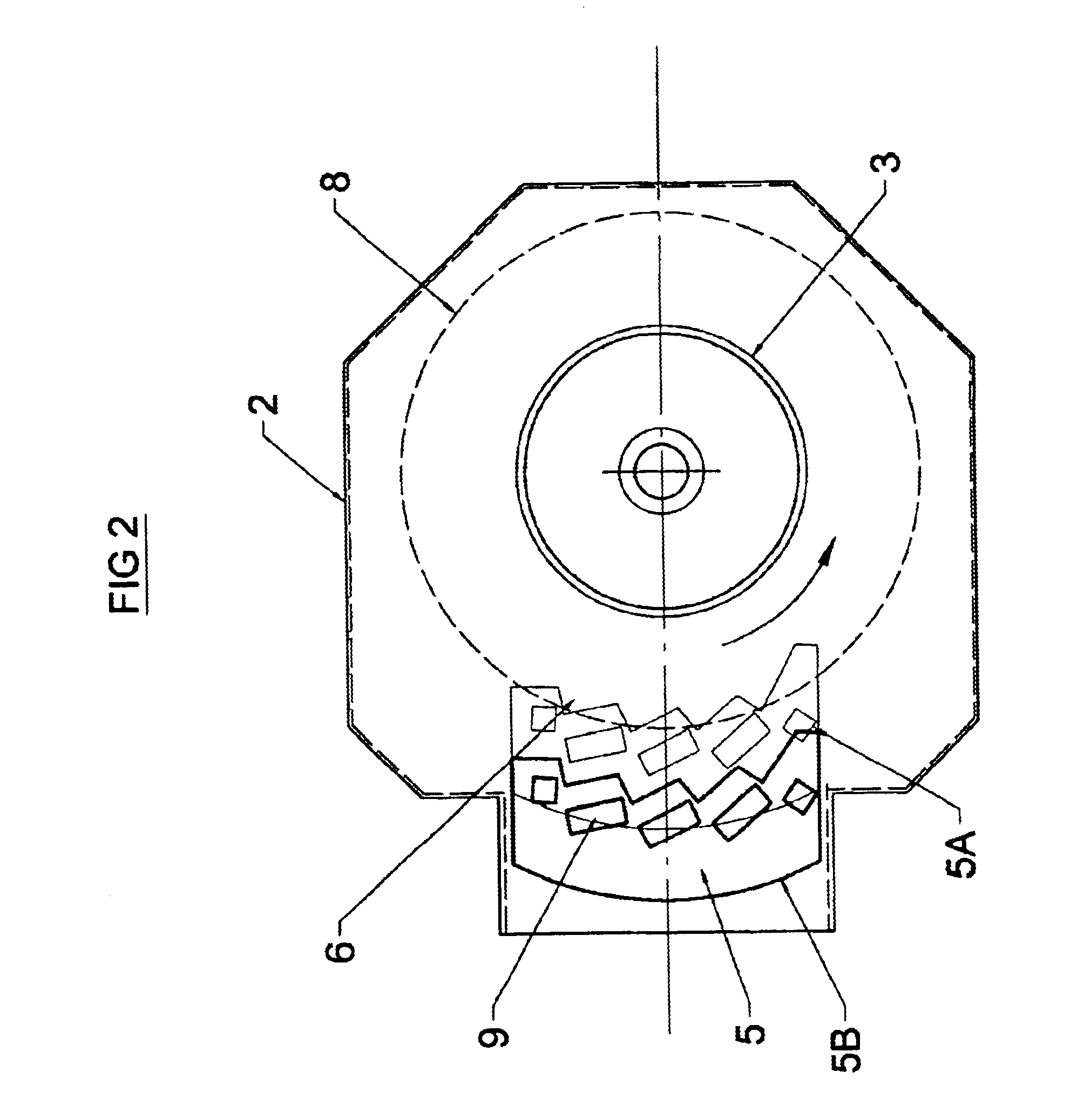
In preferred embodiments, the crusher may be configured so that where a rock swirl develops in the crushing chamber, the ever-tightening corner inside the chamber has a slowing effect on the rock swirl.
The present invention also allows the operator to adjust the settings on the rock crusher while it is operating in order to maintain the rock product specification at optimum levels at all times.

Problems solved by technology

High reduction generally gives poor shape and low strength rock which are undesirable.
Low reduction generally gives good shape and high strength which are desirable but high by-product and low output which arm undesirable.
This by-product is expensive to produce, has low commercial value and sometimes high environmental costs.
The current problem is that
existing crushers lack the control to make a variety of tight specification products at a high rate or without by-product.
These machines have good reduction but do not produce fine sand or have good shape.
These machines have high operating costs and the rock product changes rapidly as the crusher wears, i.e. they will not hold the desired rock product specification.
These machines have good reduction but high operating costs, lower rock strength, bad shape, and won't hold a desired rock product specification as they wear.
Anvil VSIs must also be stopped frequently in order to replace worn anvils, which results in expensive down-time.
These machines have high rock strength good shape and produce good sand but have low reduction, and often produce high by-product (unwanted product).

Method used


Image

  • Rock crushers
  • Rock crushers
  • Rock crushers

Examples


Embodiment Construction

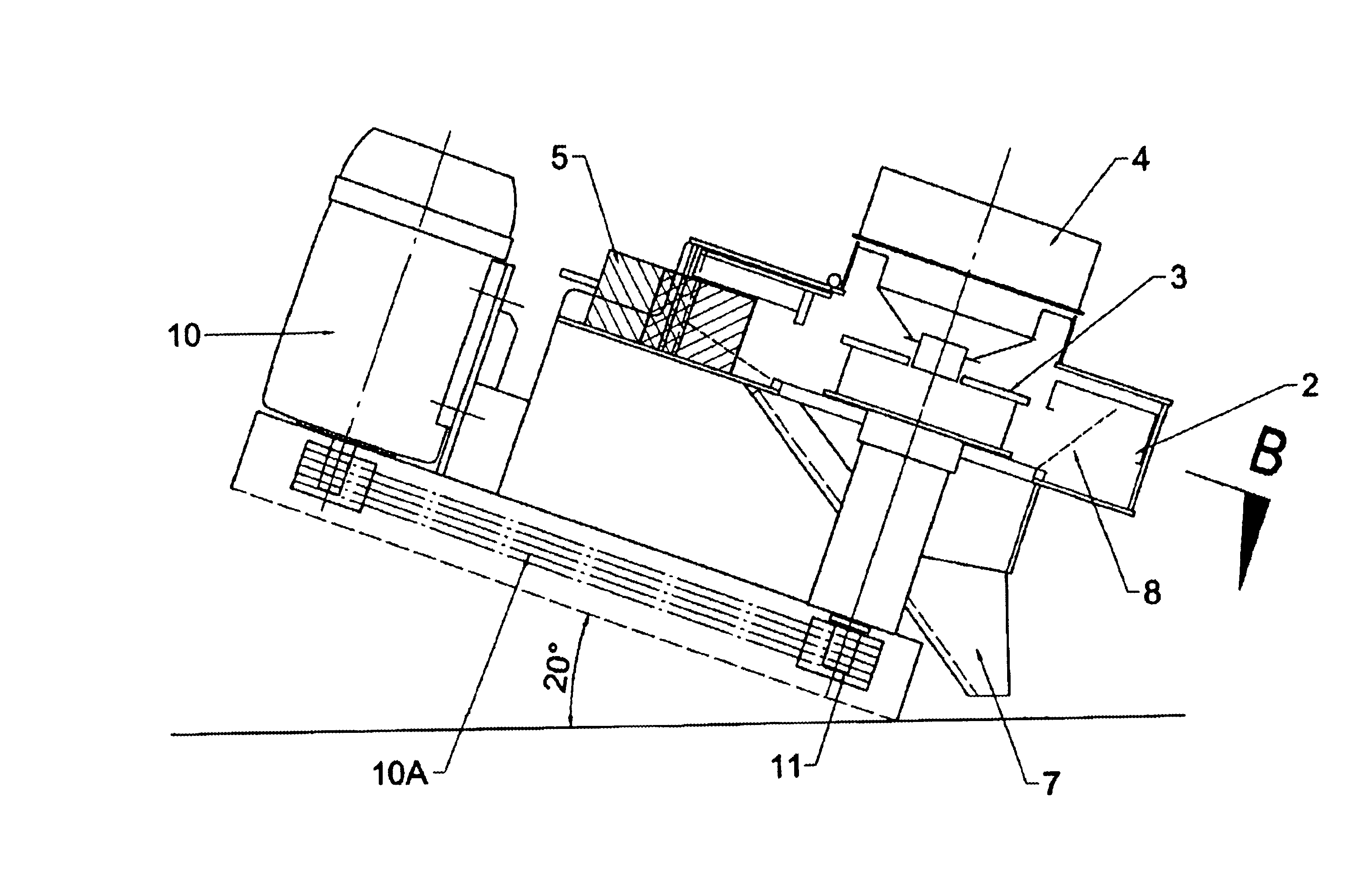
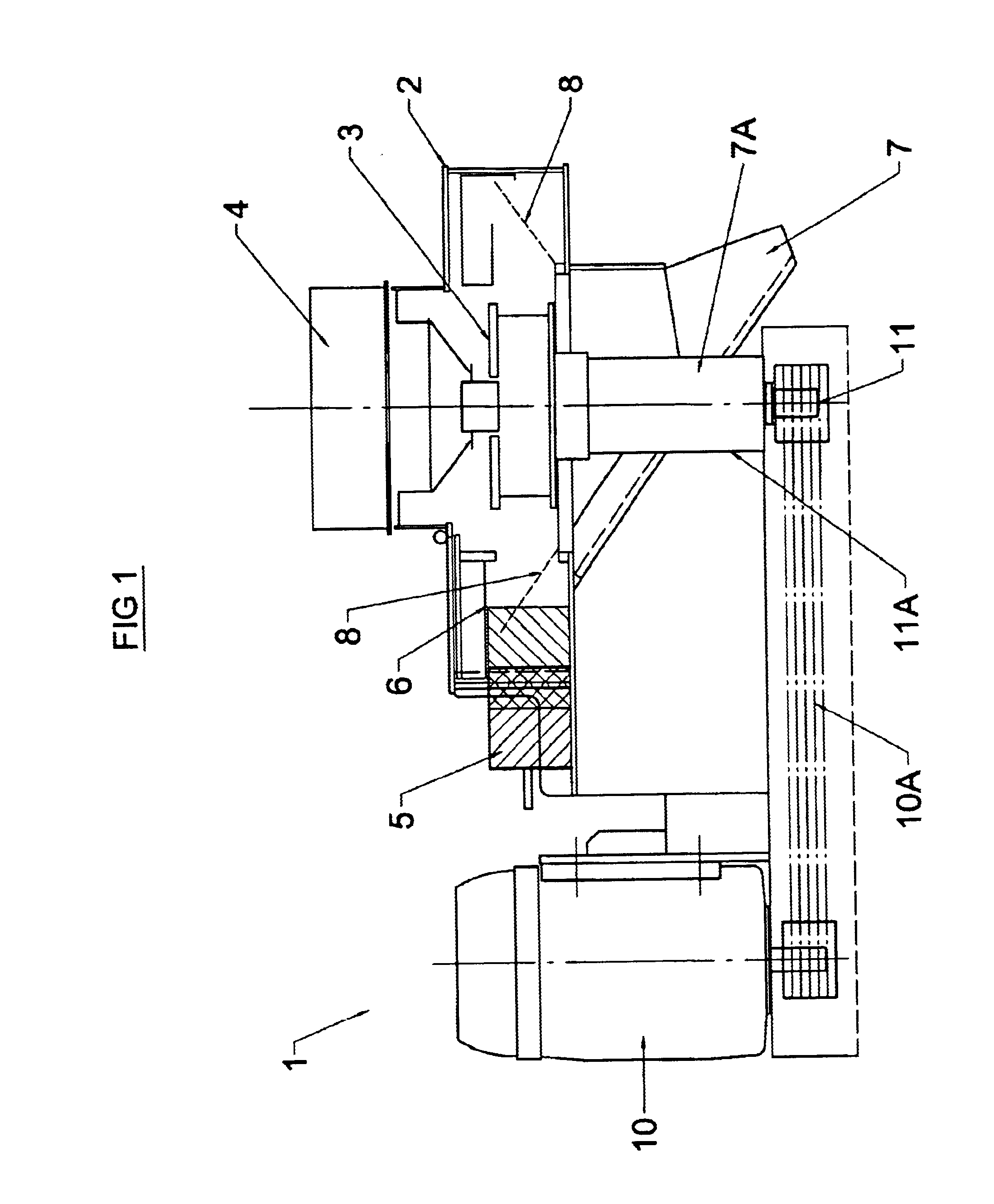
With reference to FIG. 1 thee is shown one embodiment of the present invention with the crushing chamber components in a substantially horizontal orientation.

The rock Crusher 1 includes a crushing chamber housing 2. The crushing chamber housing houses a rotor 3 into which rock is introduced via feed tube 4. The rotor 3 includes exit openings on its sides, which are not shown. The rotor spins and the rocks are flung outwards from the rotor openings at between 30-90 m / s.

The crushing chamber 2 also includes an anvil 5. The rock impact on the anvil face 6. Most of the rock that shatters as a result of impact will travel down the angled chute 7 for collection.

11A designates a shaft housing which houses the shaft 11. The shaft housing 11A may be circular or rectangular or some other polygonal shape. The configuration of the chute 7 is such that where the plane of the chute 7 intersects the shaft housing 11A at point 7A, the shaft housing passes through the chute 7 at an angle. Where the s...


PUM


Abstract

The invention relates to improvements to rock crushers, and in particular rotary impact rock crushers. The crushing chamber may be angled to achieve the desired rock product. Also disclosed is an anvil for use in crusher whereby the anvil position adjustable. The invention enables the operator to dial up a particular rock product specification by adjusting the angle of the crushing chamber and / or the position of the anvil. The adjustments may be made without ceasing the operation of the machine. Improved control over fracture mechanisms within the crushing chamber and as a consequence the rock product, are achievable with the present invention.

Description

This invention relates to improvements to rock crushers.In particular, the present invention relates to improvements in rotary) impact rock crushers which provide a greater control over the fracture mechanisms and the grade of rock product.The many end use applications for rocks require that a range of rock grades are available for use.The desirable characteristics of a rock product are that it is shaped and graded to suit the duty for which it is required and the strength of the rock is maximized.The desirable crushing characteristics of a crusher are that there is a high size reduction of the rock, shape and strength of the rock product are maintained or improved and that the crush can be controlled to maximise the desired end product.There is generally a large compromise between what a crusher will make and what rock product is required. High reduction generally gives poor shape and low strength rock which are undesirable. Low reduction generally gives good shape and high strengt...

Claims


Application Information

Patent Timeline
IPC IPC(8): B02C13/00B02C13/18B02C13/14
CPCB02C13/1835B02C2013/1871B02C2013/1878B02C2013/1885
Inventor ROBSON, ANGUS PETER
Owner BLUE PACIFIC MINERALS
Learn More