Air servo valve

a technology of air servo valve and servo valve body, which is applied in the direction of valve operating means/releasing devices, service pipe systems, transportation and packaging, etc., can solve the problems of unsuitable cases, low ratio of generated thrust/permanent magnet weight, and flow rate control

Inactive Publication Date: 2004-09-07
SMC CORP
View PDF1 Cites 22 Cited by
  • Summary
  • Abstract
  • Description
  • Claims
  • Application Information

AI Technical Summary

Benefits of technology

In the air servo valve having the above-described constitution, when the exciting coil is energized, one pole tooth of the yoke becomes N pole and the other pole tooth becomes S pole in response to the direction of the current. Then, when the magnetic pole generated in these pole teeth and the magnetic pole on the side of an outer periphery of the permanent magnet are different poles, an attracting force acts between these magnetic poles, but when they are the same pole, a repelling force acts therebetween. Therefore, the permanent magnet displaces in the axial direction due to these acting forces so that spool switching is performed. At this time, since the cylindrical permanent magnet is used as the movable body, the thrust relative to the weight of the movable body can be made larger as compared with the conventional article using the rod-like permanent magnet and the air servo valve of the present invention is superior to the conventional article in response.
On the other hand, the displacement of the permanent magnet is detected as the displacement of the spool by the displacement sensor, and the detection signal is fed back to the control circuit. Then, in this control circuit, the detection signal is compared with the set value, a control signal is outputted from the control circuit to the driving portion such that the deviation becomes zero, and the amount of displacement of the permanent magnet, namely, the amount of displacement of the spool is adjusted so that flow rate control is performed. At this time, since the flux density of the cylindrical permanent magnet which has been magnetized in the radial direction varies linearly on the center axial line, the displacement sensor is disposed so as to position on the center axial line within the hollow portion of the permanent magnet, so that the displacement of the permanent magnet can be detected accurately and flow rate control can be made with a high precision.

Problems solved by technology

However, such an electromagnet is suitable for a case that the spool is switched to two positions but it is unfit for a case that flow rate control is performed by performing feedback control on the operation position of a spool.
However, since the above-described known electromagnetic actuator uses a rod-like permanent magnet as a movable body, there is a problem that a ratio of generated thrust / permanent magnet weight becomes small due to the size of the magnet and response is poor.
Also, since N pole and S pole are magnetized in an axial direction of the permanent magnet, there is also a problem that the actuator is easily influenced by lateral load at a time of actuation thereof.
However, since the flux density is not changed linearly, it is much difficult to detect the displacement of the permanent magnet accurately.

Method used


Image

  • Air servo valve
  • Air servo valve
  • Air servo valve

Examples


Embodiment Construction

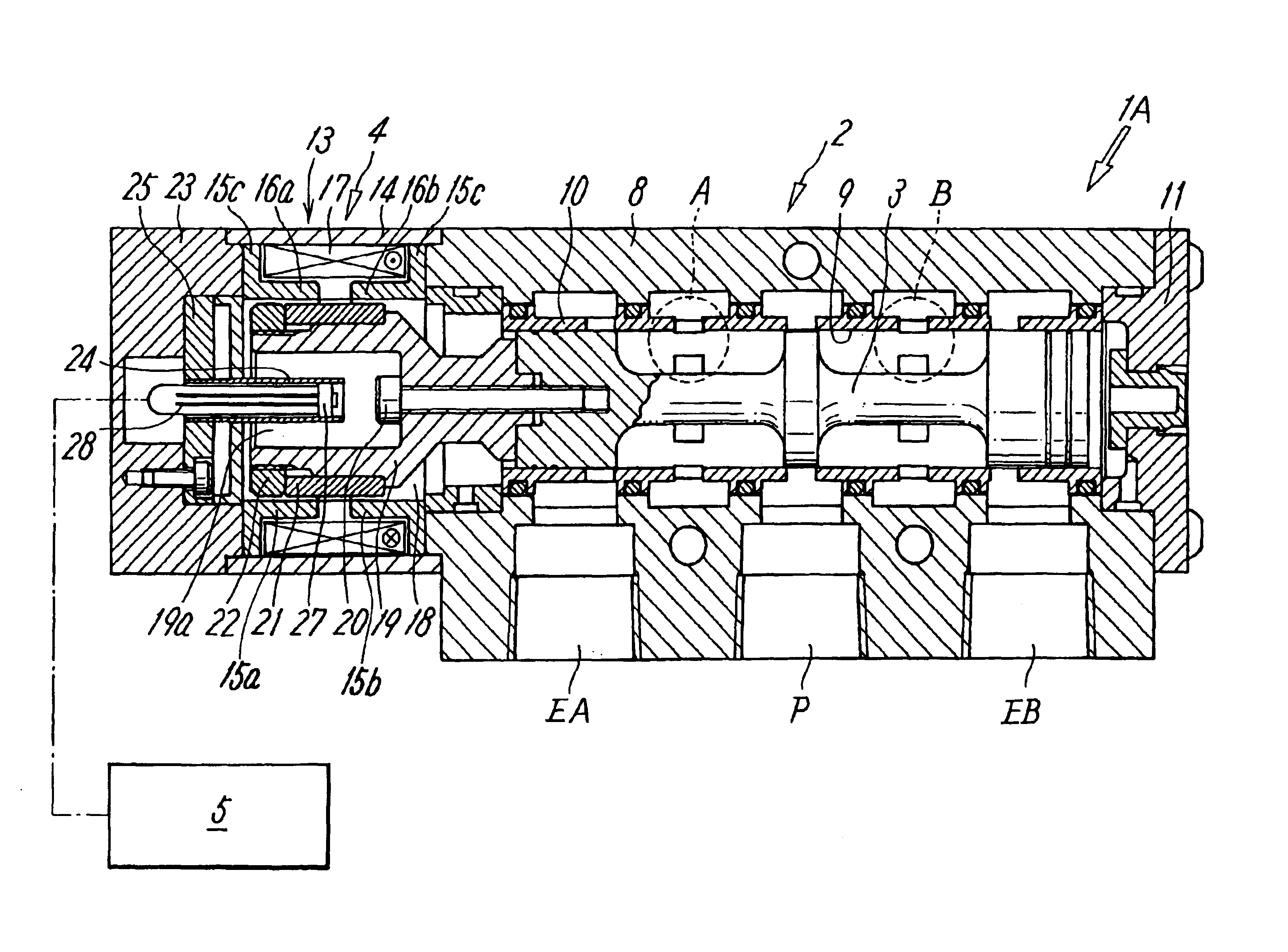
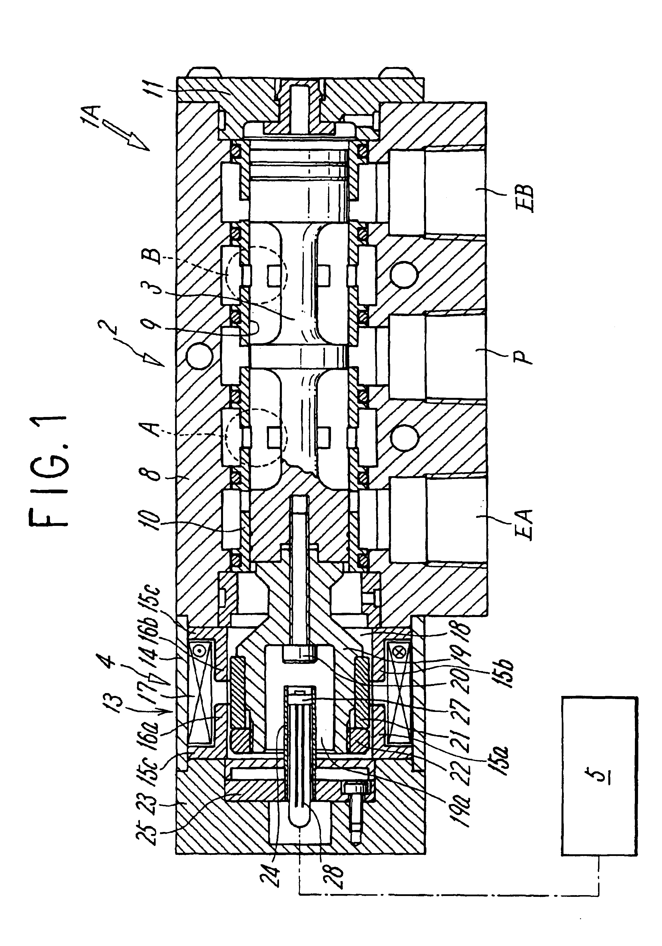
FIG. 1 shows a first embodiment of an air serve valve according to the present invention, where an air servo valve 1A comprises a valve switching portion 2 of a 5-port type which switches connection states of fluid flow paths of a spool 3, a driving portion 4 which is constituted so as to drive the spool 3 by an electromagnetic actuator, and a control portion 5 which performs feedback control on the driving portion 4.

The valve switching portion 2 has a casing 8 with a rectangular section, and a supply port P, two output ports A, B, two exhaust ports EA, EB, and a valve hole 9 are formed in this casing 8 with which the respective ports communicate. A sleeve 10 provided on a periphery with openings communicating with the respective ports is attached in this valve hole 9, and the spool 3 for switching flow paths among the respective ports is slidably accommodated in the sleeve 3. In the figure, reference numeral 11 denotes an end cover attached to one end of the casing 8.

Also, the driv...


PUM

PropertyMeasurementUnit
current flowaaaaaaaaaa
flux densityaaaaaaaaaa
voltageaaaaaaaaaa

Abstract

An exciting coil is wound on a cylindrical yoke provided with a pair of pole teeth, a cylindrical permanent magnet where N pole and S pole are magnetized in a radial direction is disposed so as to be movable in a hollow portion of the yoke and the permanent magnet is coupled to a spool by a magnet holder, and a displacement sensor is disposed in a hollow portion of the permanent magnet so as to be positioned on a center axial line of the permanent magnet, so that the displacement of the permanent magnet is detected by the displacement sensor and the degree of opening of the spool is controlled by performing feedback of the displacement to a control portion.

Description

The present invention relates to an air servo valve constituted so as to perform spool switching using an electromagnetic actuator of a magnet movable type as a drive source.PRIOR ARTConventionally, as an equipment for controlling fluid pressure supplied to a fluid pressure cylinder or the like, a switching valve of a spool type has been known. The switching valve of a spool type is constituted such that an electromagnet is used as a drive source for driving a spool and the spool is driven by a movable iron core of the electromagnet. However, such an electromagnet is suitable for a case that the spool is switched to two positions but it is unfit for a case that flow rate control is performed by performing feedback control on the operation position of a spool.In view of the above, there is an example that, when flow rate control is performed by performing feedback control on the operation position of the spool, an electromagnetic actuator of a magnet movable type is used as a drive s...

Claims


Application Information

Patent Timeline
Patent Type & Authority Patents(United States)
IPC IPC(8): F15B13/10F15B13/044F15B13/04F15B13/00F16K31/06F16K37/00H01F7/16
CPCF15B13/0402F15B13/0442F15B13/10F16K31/0613F16K37/0033F16K37/0041F15B2013/0409F15B2013/0448Y10T137/86622Y10T137/8242
Inventor YAJIMA, HISASHIFUJIWARA, NOBUHIROMATSUMOTO, DAISUKEYO, SEIKAIMIYACHI, HIROSHI
Owner SMC CORP
Why Eureka
Try Eureka