Gas lighter

a lighter and gas technology, applied in the field of gas lighters, can solve the problems of difficulty for persons with a large hand to ignite gas lighters, complicated structure of gas lighters, and deterioration of ease of operation, so as to achieve the effect of less complicated lighter structur

Inactive Publication Date: 2004-09-07
TOKAI
View PDF13 Cites 13 Cited by
  • Summary
  • Abstract
  • Description
  • Claims
  • Application Information

AI Technical Summary

Benefits of technology

an engagement projection is provided on the periphery of the side wheel so that the engagement projection on the periphery of the side wheel is engaged with an engagement portion provided on the cap to prevent rotation of the file wheel, thereby locking the lighter not to be ignited, and is disengaged from the engagement portion upon movement of the side wheel in the direction in which the flint is retracted, thereby allowing the side wheel to rotate and releasing lock of the lighter.
In the gas lighter in accordance with the present invention having a structure described above, the gas lighter can be locked not to be ignited by engaging the engagement projection on the periphery of the side wall with the engagement portion of the cap so that the side wheel cannot be rotated and the lock of the gas lighter can be released by moving the side wheel to retract the flint, thereby disengaging the side wheel from the cap. Accordingly, the gas lighter cannot be rotated by simply rotating the side wheel as in the conventional igniting action, which causes the user to recognize that the gas lighter cannot be ignited by the conventional igniting action. However, this ignition lock can be released by moving the side wheel to retract the flint, which is an action which can be easily done in a series of the igniting actions by even a large-handed person.
When the side wheel is released from the user's finger in a series of the igniting actions and the actuator lever comes to be depressed, the side wheel is automatically returned to the original position under the resilient force of the flint, where the engagement projection of the side wheel can be surely engaged with the engagement portion of the cap to lock the lighter not to be accidentally ignited.
When the side wheels are mounted on a rotary shaft which is supported by a vertical bearing hole provided in a support column on the lighter body so that the rotary shaft is rotatable and movable in the direction in which the flint is retracted, less additional components are required and the structure of the lighter is less complicated, which makes the lighter more suitable for mass production.

Problems solved by technology

However, almost all the gas lighters provided with a lock mechanism for preventing ignition by the known igniting action is arranged so that the actuator lever cannot be depressed until the lock mechanism is released or until the actuator lever is moved forward, that is, in any one of the known gas lighters provided with an ignition lock mechanism, a small member must be operated to release the lock mechanism.
Accordingly, it has been difficult for persons with a large hands to ignite the gas lighters releasing the lock mechanism and it has been demand for improving the structure of such a gas lighter toward practicability.
In other words, in a gas lighter having a lock mechanism which is to be released by an action deviated from the igniting action of operating the side wheel and the actuator lever in this order, the lock release action is troublesome and the ease of operating the light is deteriorated, and at the same time, the gas lighter is complicated in its structure.

Method used


Image

  • Gas lighter
  • Gas lighter
  • Gas lighter

Examples


first embodiment

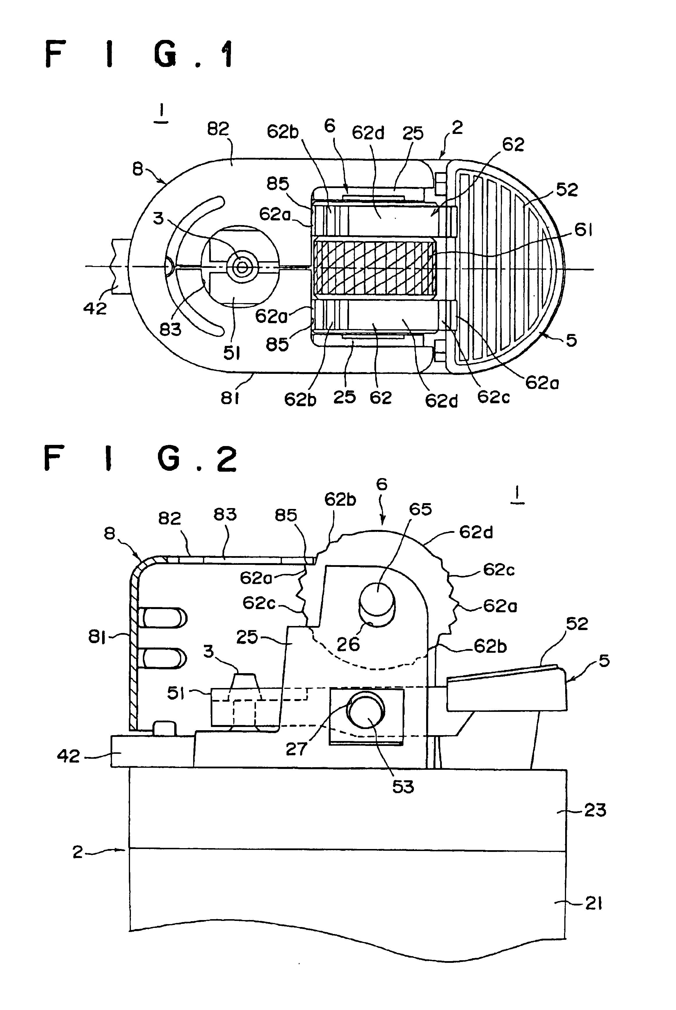
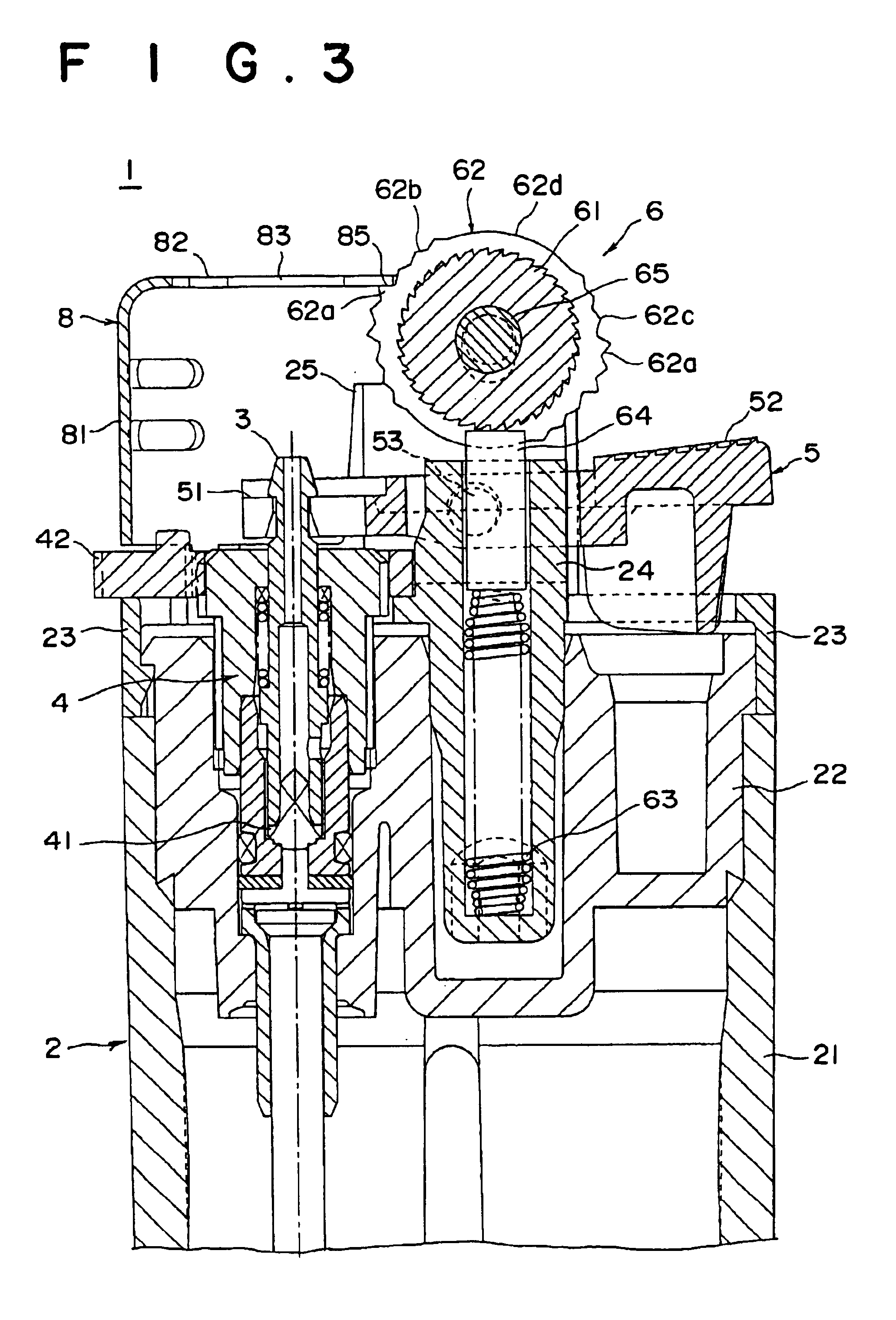
FIG. 1 is a plan viewing showing a gas lighter in accordance with a first embodiment of the present invention in a state where it is not used, FIG. 2 is a fragmentary front view partly in cross-section of the lighter, and FIG. 3 is a vertical cross-section view of the lighter. In the following description, the left in FIG. 1 will be expressed as the front of the lighter, the right will be expressed as the rear of the lighter and the up-and-down direction will be expressed as the left and right direction.

The gas lighter 1 of this embodiment comprises a lighter body 2 in which fuel gas is stored, a fuel supply means 4 comprising a nozzle 3 through which fuel gas is ejected and a valve mechanism 41, an actuator lever 5 which lifts the nozzle 3 to open the valve mechanism 41, and file-type ignition means 6.

The lighter body 2 comprises a bottomed tubular reservoir body 21 formed of synthetic resin and an upper lid 22 air-tightly fixed to the upper side of the reservoir body so that a res...

second embodiment

FIG. 6 is a fragmentary front view showing an important part of a gas lighter in accordance with a second embodiment of the present invention and FIGS. 7A to 7B are views for illustrating different states of the side wheel during rotation for igniting the gas lighter of the second embodiment.

The gas lighter 1 of this embodiment is different from that of the first embodiment in the shape of the rotary shaft 165 of the side wheels 62 and the bearing hole 126 formed in each of the support columns 25 is substantially the same as that of the first embodiment in the basic structure of the lighter body 2, the nozzle 3, the fuel supply means 4, the actuator lever 5, the ignition means 6, and accordingly, the elements analogous to those in the first embodiment are given the same reference numerals and will be described here.

As in the first embodiment, the side wheels 62 of the ignition means 6 are fixed to opposite sides of the file wheel 61 to be integrally rotated therewith and the flint 6...


PUM


Abstract

A gas lighter in which the lighter is locked not to be accidentally ignited by preventing rotation of the side wheel and the lock can be released by an action which can be included in a series of the igniting actions of operating the side wheel to rotate the file wheel to generate a spark and depressing the actuator lever to eject the fuel gas so that even a large-handed person can be easily operate the gas lighter. The ignition means comprises a file wheel, a pair of side wheels fixed to the opposite faces of the file wheel to be rotated integrally therewith and a flint which is in abutment against a lower portion of the file wheel. The rotary shaft of the side wheels are supported for rotation and movement in a direction in which the flint is retracted. An engagement projection formed on the periphery of the side wheels is engaged with an engagement portion on a cap to prevent rotation of the file wheel, thereby locking the lighter not to be ignited. The engagement projection is disengaged from the engagement portion in response to movement of the side wheels in the direction in which the flint is retracted, thereby releasing lock of the lighter.

Description

This invention relates to a gas lighter in which the fuel gas is ejected and ignited in response to rotation of a side wheel (to rotate a file wheel) and depression of an actuator lever and in which ignition is prevented when the side wheel is in the normal position.As disclosed, for instance, in U.S. Pat. Nos. 5,197,870, 5,165,885, 5,634,787 and 5,490,773, there has been known a flint-type gas lighter in which the actuator lever which is depressed to lift the ejector nozzle and cause the nozzle to eject the fuel gas is arranged to be able to cause the nozzle to eject the fuel gas only when it is depressed while being slid.There have been further proposed various gas lighters which are arranged not to be ignited by simply rotating the side wheel and depressing the actuator lever.However, almost all the gas lighters provided with a lock mechanism for preventing ignition by the known igniting action is arranged so that the actuator lever cannot be depressed until the lock mechanism is...

Claims


Application Information

Patent Timeline
Patent Type & Authority Patents(United States)
IPC IPC(8): F23Q2/16F23Q2/00
CPCF23Q2/161F23Q2/164
Inventor SAITO, MASAKI
Owner TOKAI
Why Eureka
Try Eureka