LED matrix moldule

Inactive Publication Date: 2004-09-07
HSIUNG BEAR
View PDF25 Cites 113 Cited by
  • Summary
  • Abstract
  • Description
  • Claims
  • Application Information

AI Technical Summary

Benefits of technology

to provide an LED matrix module with increased brightness, reduced size,

Problems solved by technology

In the above LED matrix structure, the brightness of the LED structure usually deteriorates due to poor heat dissipation.
Furthermore, since the LED matrix is mounted on the circuit board and molded to form the casing, the whole LED matrix structure is undesirably thick.
The complex manufacture process further reduces the yield and th

Method used


Image

  • LED matrix moldule
  • LED matrix moldule
  • LED matrix moldule

Examples


Example

Wherever possible in the following description, like reference numerals will refer to like elements and parts unless otherwise illustrated.

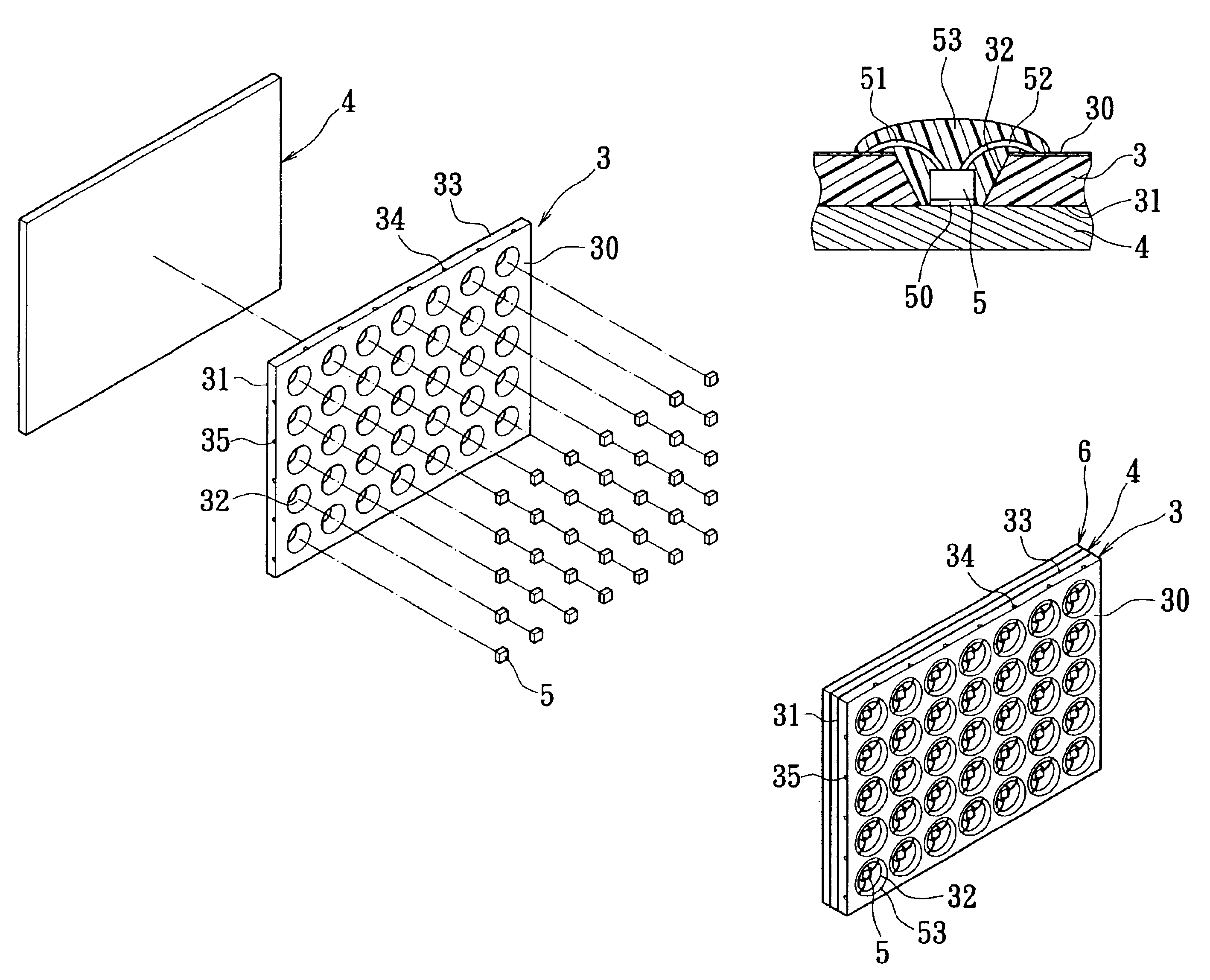
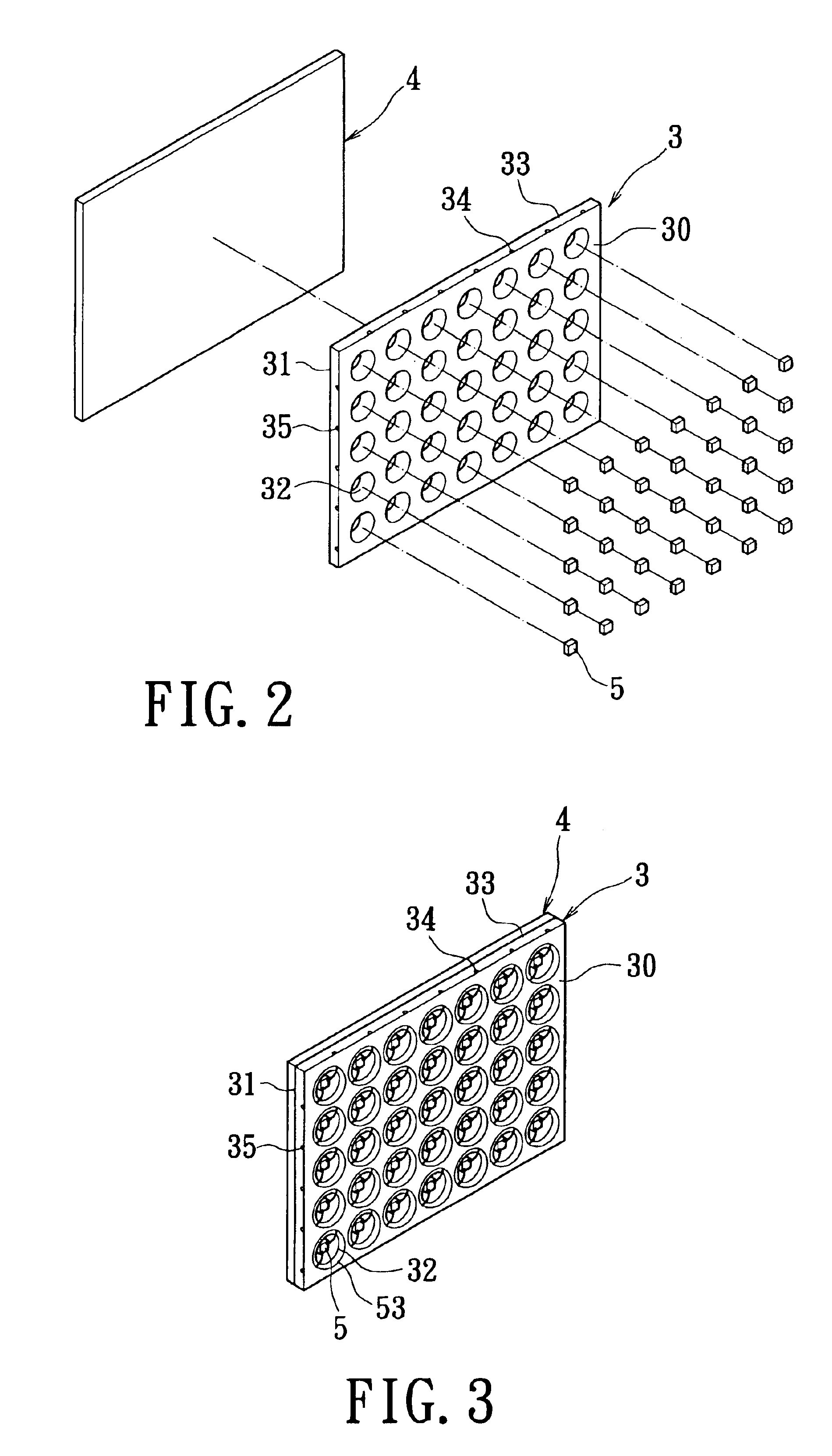
Referring to FIG. 2 to FIG. 4, the invention provides an LED matrix module including a circuit board 3, a thermally conductive plate 4 and a plurality of LED chips 5.

The circuit board 3 has a circuit surface 30 and a bonding surface 31 opposite the circuit surface 30. The circuit board 3 has a plurality of slots 32 formed through the circuit surface 30 and the bonding surface 31. The circuit board 3 is, for example, a bi-layered or multi-layered circuit board. A positive trace 34 and a negative trace 35 respectively extend from an edge 33 of the circuit board 3.

The thermally conductive plate 4 is attached onto the bonding surface 31 of the circuit board 3. The thermally conductive plate 4 is a metal plate with a reflective anti-oxidation material applied thereon.

The LED chips 5 are respectively mounted in the slots 32 of the circuit board 3 and t...


PUM


Abstract

An LED matrix module of the invention has a circuit board, a thermally conductive plate and a plurality of LED chips. A plurality of slots is formed through a circuit surface and a bonding surface of the circuit board. A positive trace and a negative trace respectively extend from an edge of the circuit board. The thermally conductive plate is attached onto the bonding surface of the circuit board. The LED chips are respectively mounted through the slots of the circuit board in a manner to attach on the thermally conductive plate. Each LED chip is further electrically connected to the positive and negative traces on the circuit surface of the circuit board respectively via a positive electrode wire and a negative electrode wire. The LED chips are directly attached onto the thermally conductive plate through which the heat dissipates. The high brightness of the LED is thereby ensured.

Description

1. Field of the InventionThe invention relates to an LED matrix module and, more particularly, to an LED matrix module in which a plurality of LED chips are respectively mounted through slots formed through a circuit board.2. Description of the Related ArtThe association of photoelectric elements into visual signs enables the creation of light effects that increase visual attention. When an LED matrix structure is integrated into a commercial signboard, the advertisement layout is outlined over the light from the LED matrix to render the advertisement more visible and attractive. Therefore, the photoelectric element must be provided with enough brightness to attract the attention of a passerby. However, an effective heat dissipation of the highly bright light is critical for maintaining a normal operation of the photoelectric element. Furthermore, the signboard usually has a large area. Therefore, an effective assembly process is needed to easily and efficiently assemble the large s...

Claims


Application Information

Patent Timeline
IPC IPC(8): G09F9/33H01L25/075H01L33/00H01L33/64
CPCG09F9/33H01L25/0753H01L33/62H01L33/64H01L2924/15153H01L2924/1517H01L2224/73265H01L2224/48091H01L2924/00014H01L2924/00F21V21/096F21Y2101/02F21Y2105/001F21Y2105/10F21Y2115/10
Inventor HSIUNG, BEAR
Owner HSIUNG BEAR
Why Eureka
Try Eureka