Clutch system

a technology of clutches and operating mediums, applied in the direction of fluid-actuated clutches, non-mechanical actuated clutches, clutches, etc., can solve the problem that the clutch also requires a comparatively high volume flow rate of the operating medium

Inactive Publication Date: 2004-09-14
ZF FRIEDRICHSHAFEN AG
View PDF8 Cites 73 Cited by
  • Summary
  • Abstract
  • Description
  • Claims
  • Application Information

AI Technical Summary

Benefits of technology

By prefilling or partially filling the slave cylinder with the second medium provided by the second pump arrangement with the use of a bypass around the first pump arrangement, comparatively short switching times are obtained, and a first pump arrangement with an especially low delivery volume may be used. These advantages are derived from the fact that, to fill the slave cylinder of a wet-running clutch to increase the pressure from zero to approximately 20% of the maximum pressure, it is necessary to supply about 90% of the filling volume (merely by way of example) which the slave cylinder has at maximum pressure. A fraction of the maximum pressure on the order of magnitude cited (for example, 20%) can also be produced by a typical coolant pump such as the second pump arrangement. Accordingly, the second pump arrangement may be used to prefill or partially to fill the slave cylinder to a significant extent (e.g., to the above-cited 90% of its volume), whereas the first pump arrangement is used primarily to fill the slave cylinder from that point on to produce even higher pressures.
Alternatively, the slave cylinder may be connected to the delivery side of the second pump arrangement such that it bypasses an open loop / closed loop valve arrangement installed between the first pump arrangement and the slave cylinder. This latter design allows an open loop / closed loop valve arrangement with a very small effective flow cross section to be used without limiting or impairing the reduction in the switching times obtained as a result of the prefilling or partial filling.
In conjunction with the prefilling or partial filling, it is also proposed that a section of the operating medium system downstream from the second pump arrangement have an effective flow cross section which is dimensioned such that a pressure level is reached on the delivery side of the second pump arrangement which allows the slave cylinder to be partially filled or prefilled to a technically relevant extent the second with medium provided by the second pump arrangement. Alternatively, at least one pressure-adjusting or pressure-increasing device may be provided in a section of the operating medium system downstream from the second pump arrangement, for setting a pressure level on the delivery side of the second pump arrangement which allows the slave cylinder to be partially filled or prefilled to a technically relevant extent with medium provided by the second pump arrangement. The pressure adjusting or pressure increasing device may comprise at least one throttle or orifice plate and / or at least one pressure-relief valve or pressure-reducing valve. Furthermore, the pressure-adjusting or pressure-increasing device may be switchable between a first state, in which it has the effect of adjusting the pressure level, and a second state, in which it does not have an adjusting effect on the pressure level. In the second state, the operating medium may then be supplied (to cool the friction linings or disks, for example) without being affected or hindered by the pressure-adjusting or pressure-increasing device of the clutch device.

Problems solved by technology

The clutch also requires, however, a comparatively high volume flow rate of the operating medium at comparatively low pressure to cool the friction linings or disks.

Method used


Image

  • Clutch system
  • Clutch system
  • Clutch system

Examples


Embodiment Construction

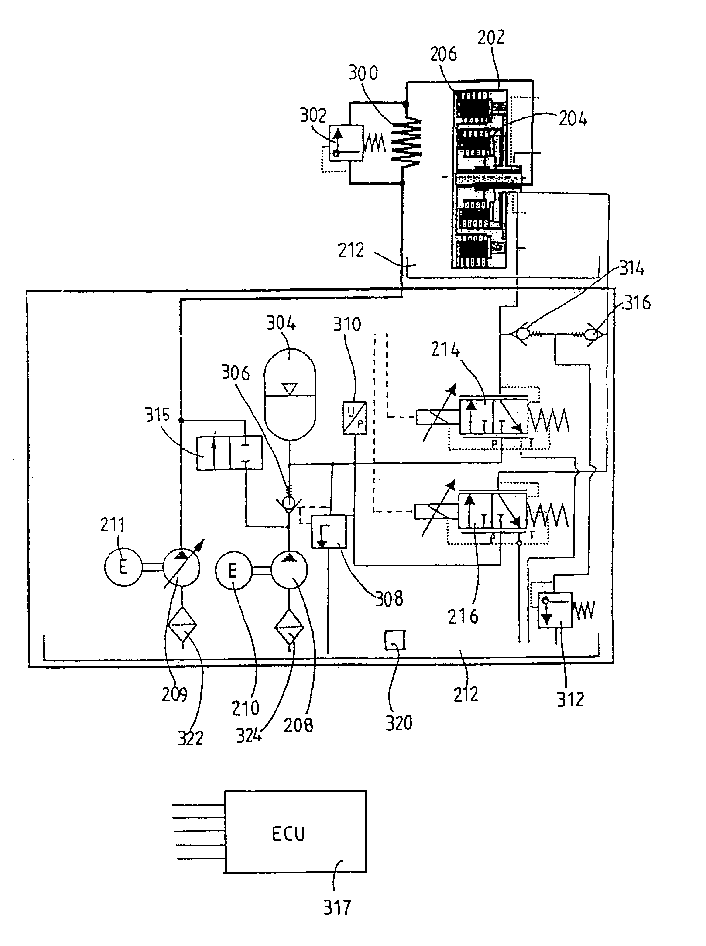
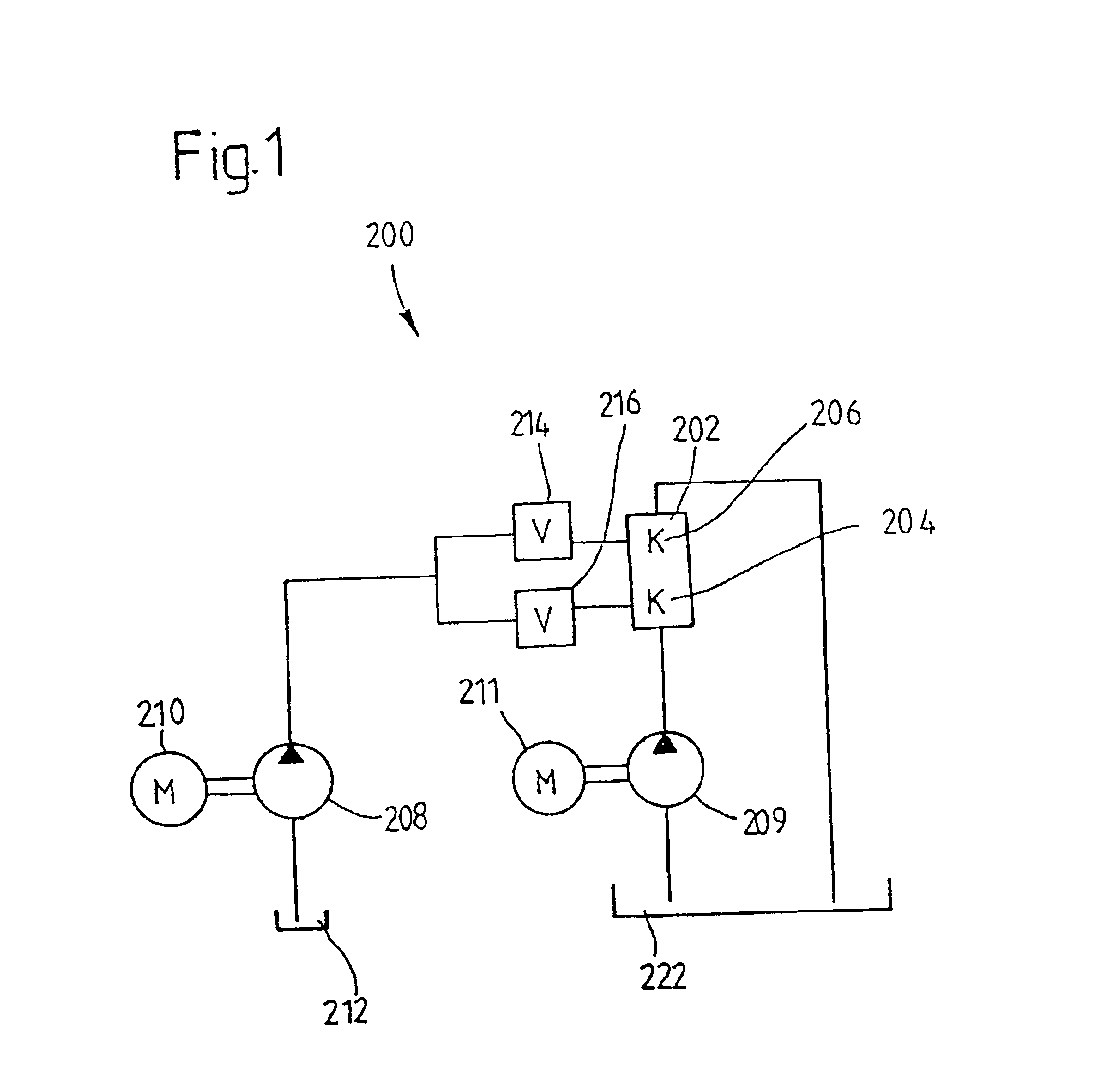
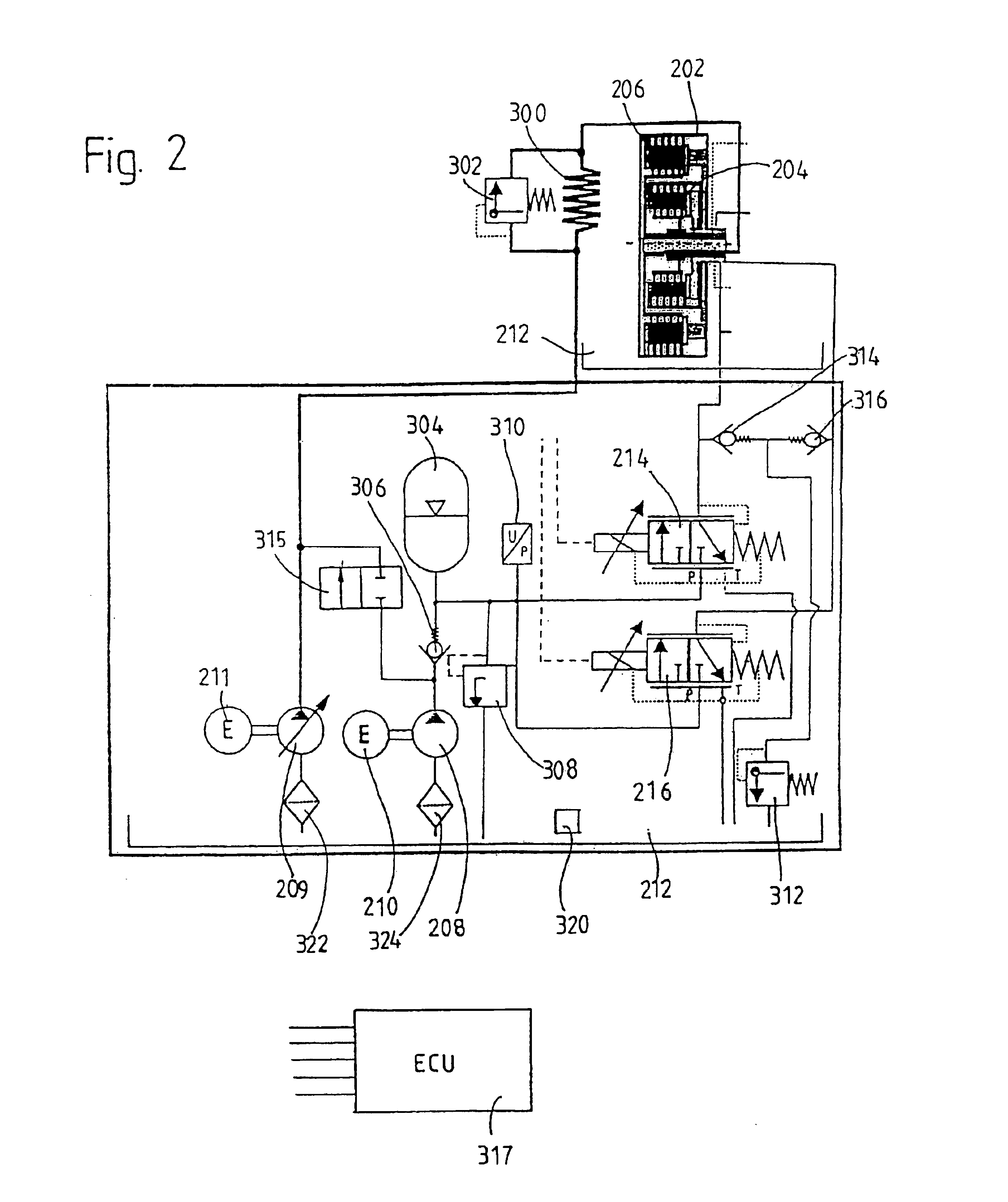
FIG. 1 is a schematic diagram of a clutch system 200 that includes a wet-running dual clutch 202 with a first radially outer clutch arrangement 206 and a second radially inner clutch arrangement 204. The first and second clutch arrangements 204 and 206 are wet- running type such as wet-running multi-disk clutch arrangements. Each of the first and second clutch arrangements 204 and 206 has at least one set of disks, one set being arranged radially above the other in the present embodiment, and each of which is actuated by an associated actuating piston of a hydraulic slave cylinder integrated into the dual clutch. Examples of dual clutches of this type are disclosed in U.S. Patent Application Serial No. 09 / 678,442, filed on Oct. 2, 2000 (now U.S. Pat. No. 6.464.059).

The clutch system 200 also includes two independent pumps, namely, a first pump 208 and a second pump 209, which are preferably driven by separate electric motors 210, 211. The first pump 208 may, for example, be designed...


PUM


Abstract

A clutch system includes a clutch device with at least one clutch arrangement for installation in a motor vehicle drive train between a drive unit and a transmission. The at least one clutch arrangement is actuated by a slave cylinder using a pressure medium which is supplied to the clutch device by a first pump. A further medium is also supplied to the clutch device by a second pump arrangement as an operating medium used during operation of the clutch device. The further medium is selectively supplied as a pressure medium to the slave cylinder.

Description

1. Field of the InventionThe present invention relates to a clutch system comprising at least one clutch device for installation in a motor vehicle drive train between a drive unit and a transmission, the clutch device having at least one clutch arrangement which can be actuated by a pressure medium and which is operated by the action of an operating medium, the pressure medium being provided by a first pump arrangement and the operating medium being supplied to the clutch device by a second pump arrangement.2. Description of the Related ArtThe present invention is based on a clutch system with the basic design described in German Patent Applications No. 100 56 954.4 of Nov. 17, 2000 and No. 101 02 874.1 of Jan. 23, 2001, which claims the priority of German Patent Application No. 100 56 953.7 of Nov. 17, 2000. The contents of these German patent applications are incorporated in their entirety by reference in the disclosure of the present application and the proposals made in those d...

Claims


Application Information

Patent Timeline
Patent Type & Authority Patents(United States)
IPC IPC(8): F16D48/04F16D48/00F16D48/02F16D48/06
CPCF16D25/14F16D48/02F16D48/0206F16D48/04F16D2300/14F16D2048/0275F16D2048/0236F16D2048/0212F16D2048/0281F16D2048/0239F16D2500/3026F16D2500/3056
Inventor BUSOLD, THOMASSCHNEIDER, HANS-JURGENBRAND, RAINERREISSER, WOLFGANGMOSELER, OLAFKUHSTREBE, JOCHENGROSSPIETSCH, WOLFGANGROHM, AXELJOHN, THOMASWIRTH, THOMAS
Owner ZF FRIEDRICHSHAFEN AG
Why Eureka
Try Eureka