
Riser tensioning construction

Inactive Publication Date: 2004-09-14
SINGLE BUOY MOORINGS INC
View PDF37 Cites 14 Cited by
  • Summary
  • Abstract
  • Description
  • Claims
  • Application Information

AI Technical Summary

Benefits of technology

It is therefore an object of the present invention to provide a riser and / or tendon tensioning construction which can be used in deep waters using a dry production tree, which consumes relatively little space and which is stable under different motions of the vessel. It is a further object of the present invention to provide a riser tensioning construction which allows attachment of multiple risers while maintaining a substantially equalised tensional force on the risers upon movements of the vessel. It is a further object of the present invention to provide a riser tensioning system which can also function as a stable support platform for production or drilling equipment. It is another object of the present invention to provide a tensioning construction which can be used in deep waters to support a metal pipe, or riser, passing from a sub sea structure to a deck supported on a floating vessel. The risers may convey hydrocarbon well production fluids to production trees on the riser supporting deck, or alternatively be used to convey flow between the sub sea structure and the deck. The upper and lower connections of the risers may be rigid with bending taking by the pipe, or may include pivoting means.
By placing the counterweight below water level, the forces exerted by the counterweight on the vessel upon movement thereof are reduced and the motions of the counterweight are damped. Furthermore, location below water level of the counterweight provides for an easy way of varying the tensional force exerted thereby, not only by varying the mass thereof but also by varying the buoyancy.
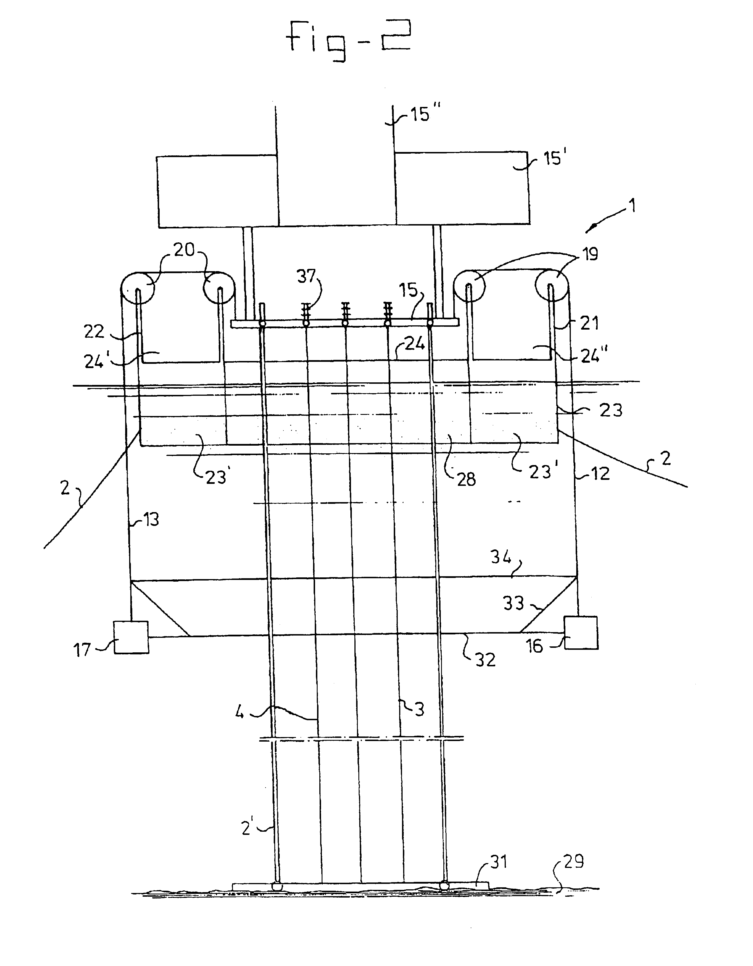
The connector can for instance be formed by a support arm extending between the mounting arms in the length or width direction of the vessel. The support arm, preferably supporting multiple risers, is lowered or raised a small amount that is determined by the elasticity of the risers, at the respective side at which the tension in the riser increases or decreases by lifting or lowering of the counterweights. Besides dynamic forces acting on the counterweights and frictional forces in the cable guide means, the tensional forces on the risers remain substantially constant and are substantially independent of the movements of the vessel. Furthermore, the support arm can be effectively used as, or be part of a stable deck structure for supporting drilling or production equipment, as it will be maintained in a substantially horizontal position by the tensional forces of the risers acting therein.
To prevent lateral motions of the tensioning weight it is possible to provide a weight guiding element on the vessel, for instance near keel level or near the seabed. It is also possible to guide the tensioning weights along the risers, in case a rigid steel casing is used.

Problems solved by technology

The known system has as a disadvantage that it takes up a lot of space and that during roll, pitch or heave movements of the vessel the large mass of the tensioning construction can give rise to an unbalance and exerts large forces on the supporting frame structure.
This system has as a disadvantage that the tensional forces exerted on the riser will vary with the buoyancy of the vessel.
In order to obtain a relatively large stroke of the cylinders the cylinders should be relatively long and therefore take up a lot of space, which in view of the moving nature of the cylinders cannot be effectively used.
Furthermore, the hydraulic system is relatively complex.
This construction has as a disadvantage that upon movement of the barge relatively large inertia forces may be exerted on the sheaves by the counter weights, and that large forces are exerted on the cables by the swinging counterweights.
Furthermore, the freely swinging counterweights may form an obstruction for personnel on deck of the drilling barge, and take up a lot of space as they should be clear from any structural parts of the barge, especially in situations of high seas.

Method used


Image

  • Riser tensioning construction
  • Riser tensioning construction
  • Riser tensioning construction

Examples


Embodiment Construction

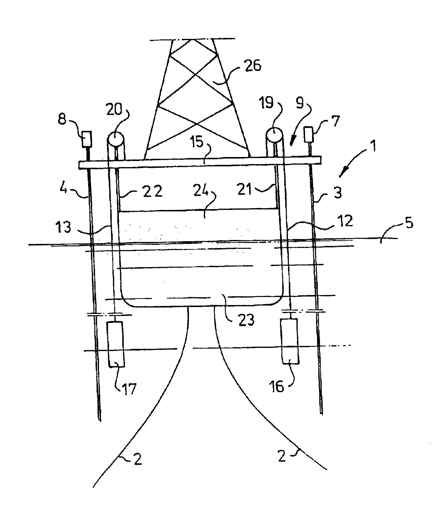
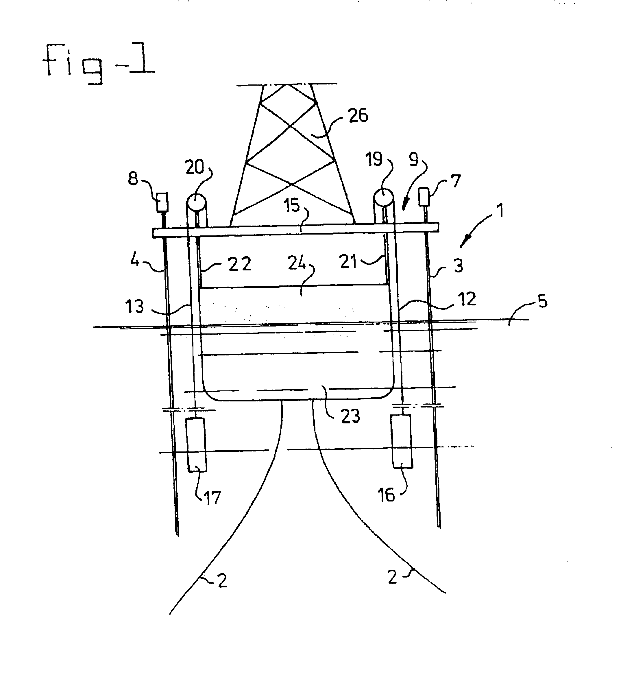
FIG. 1 shows vessel 1, such as for instance a floating storage and production vessel which is moored to the seabed via catenary anchor lines 2. As used herein the word "vessel" is intended to mean any floating construction such as semi-submersibles, floating production vessels, tension leg platforms, barges etc.. The vessel can be anchored to the seabed via anchor lines or ropes or via tendons or tethers. Within the scope of the present invention also vessels are comprised which are connected to the seabed only via one or more risers for the supply of hydrocarbons from the subsea structure to the vessel.

From a subsea well head, which may be at a depth of for instance 1000 or 2000 metres, two hard casing steel risers 3, 4 extend up to above water level 5 and are supported by the buoyancy of the vessel 1. The upper ends 7, 8 of the risers 3, 4 are attached to a tensioning member 9 comprising two cables 12, 13 being at one end attached to a connector such as a transverse support arm or...


PUM


Abstract

A vessel includes a riser and / or tendon tensioning construction. A connector, such as an arm or deck structure, is suspended from cables movable relative to cable guides. The connector carries two or more risers and / or tendons extending from a subsea structure to above water level. The free ends of the cables are attached to weights for exerting a tensioning force on the risers, which are substantially decoupled from pitch, roll and heave motions of the vessel.

Description

BACKGROUND OF THE INVENTIONThe invention relates to a vessel comprising a riser or tendon tensioning construction having at least two spaced apart mounting points and a connector carrying two or more risers or tendons which are with one end attached to the seabed and with the other end attached to the connector, the connector being suspended from the mounting points by at least two suspension members which are movably connected to the mounting points, the suspension members being with a first end attached to respective positions on the connector and with their second end to a respective tensioning member for exerting a tensioning force on the risers or tendons.From U.S. Pat. No. 4,567,842 a mooring system for a floating production vessel is known comprising a riser which is tensioned by a weight type motion compensating system. Herein the tensioning construction comprises a pivotable frame at the bow of the vessel which at one end is provided with a large counterweight near deck lev...

Claims


Application Information

Patent Timeline
IPC IPC(8): B63B35/44E21B19/00E21B7/12E21B7/128
CPCB63B35/4413E21B19/006E21B7/128
Inventor POLLACK, JACK
Owner SINGLE BUOY MOORINGS INC
Learn More