
Spread spectrum communication apparatus

a spectrum communication and spectrum technology, applied in the direction of electrical equipment, radio transmission, transmission, etc., can solve the problems of not getting the correlation between pn codes corresponding to various offsets (or phase offsets) and receiving disturbances, and achieve the effect of high speed

Inactive Publication Date: 2004-09-21
SONY CORP +1
View PDF7 Cites 66 Cited by
  • Summary
  • Abstract
  • Description
  • Claims
  • Application Information

AI Technical Summary

Benefits of technology

A second object of the present invention is to provide a spread spectrum communication apparatus in which a service of a high speed data transmission is performed at a high quality in a low signal electric power (Eb / No) environment as well as a service mainly performing a low speed data transmission such as an audio data transmission while stably holding a synchronization with a transmission signal in the low signal electric power Eb / No environment and stably performing a phase detection for the transmission signal in a synchronized condition.
In this spread spectrum communication apparatus, even though the particular string of coded symbols is punctured in the spread spectrum signal transmitting apparatus, puncture symbols are inserted into puncture positions of one string of divided demodulation symbols corresponding to the particular string of coded symbols. Therefore, each string of coded symbols can be punctured in the spread spectrum signal transmitting apparatus, so that a data transfer rate of the output data transmitted from the spread spectrum signal transmitting apparatus can be improved, and the output data can be transmitted at a high speed.

Problems solved by technology

As a result, the incoming waves originated in the transmission signal interfere with each other, so that a receiving disturbance occurs on the receiving side.
However, in cases where a pseudo noise (PN) code used for the spread spectrum of the transmission signal is offset in point of time, a correlation among PN codes corresponding to various offsets (or phase offsets) is not obtained.

Method used


Image

  • Spread spectrum communication apparatus
  • Spread spectrum communication apparatus
  • Spread spectrum communication apparatus

Examples


first embodiment

(First Embodiment)

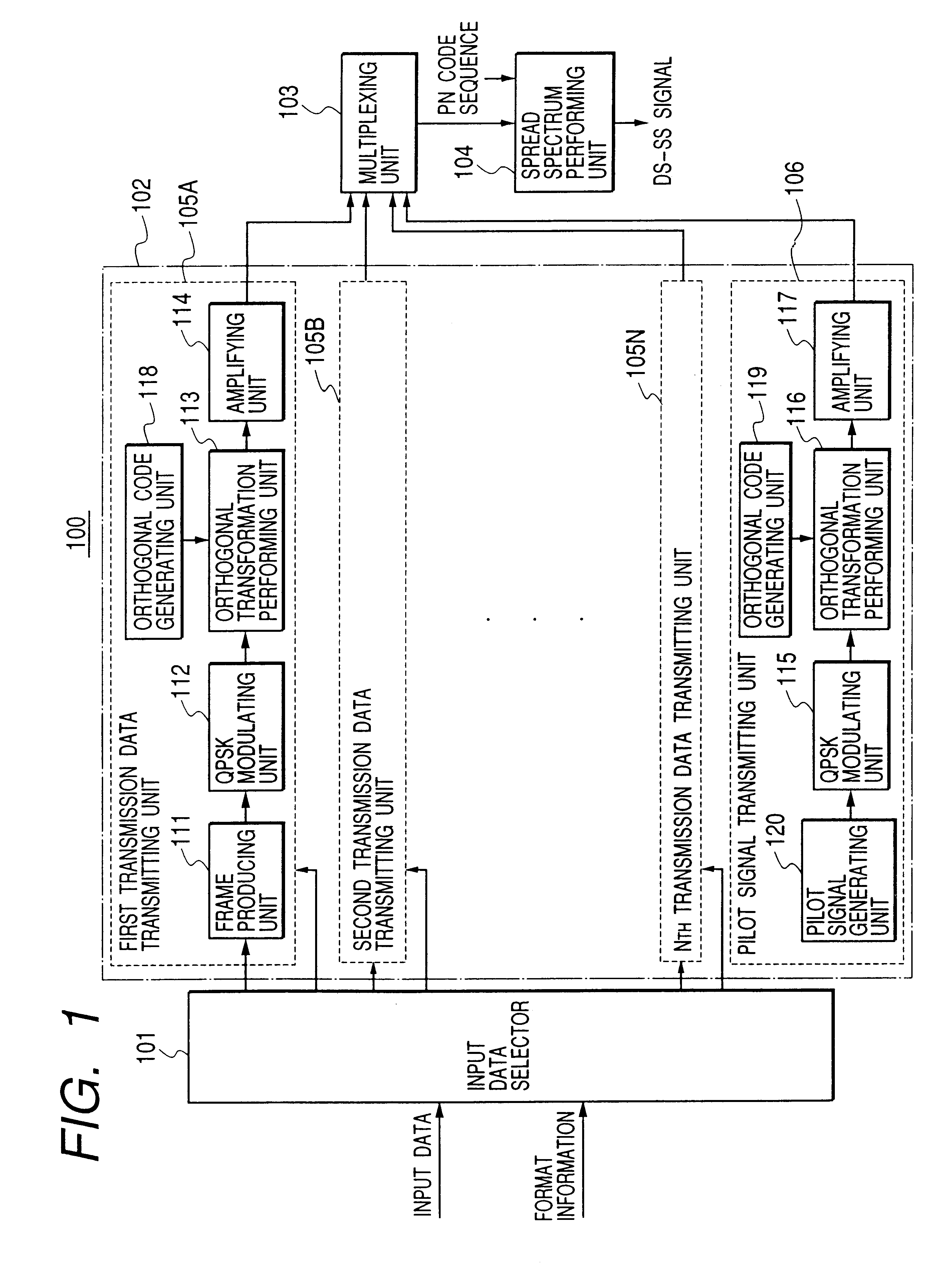
FIG. 1 is a block diagram of a spread spectrum signal transmitting apparatus of a spread spectrum communication apparatus according to first and second embodiments of the present invention.

As shown in FIG. 1, a spread spectrum signal transmitting apparatus 100 comprises:

an input data selector 101 for receiving format information and a plurality of pieces of input data respectively corresponding to a data transfer rate (or a data speed), a communication quality and an importance degree and selecting each of the pieces of input data according to the format information;

a data transmitting unit 102, corresponding to a plurality of code channels, for transforming one piece of input data selected by the input data selector 101 for each code channel to produce pieces of transmission data, generating a pilot signal, transmitting pieces of transmission data through the code channels and transmitting the pilot signal through a pilot channel allocated as one code channel;

a mu...

second embodiment

(Second Embodiment)

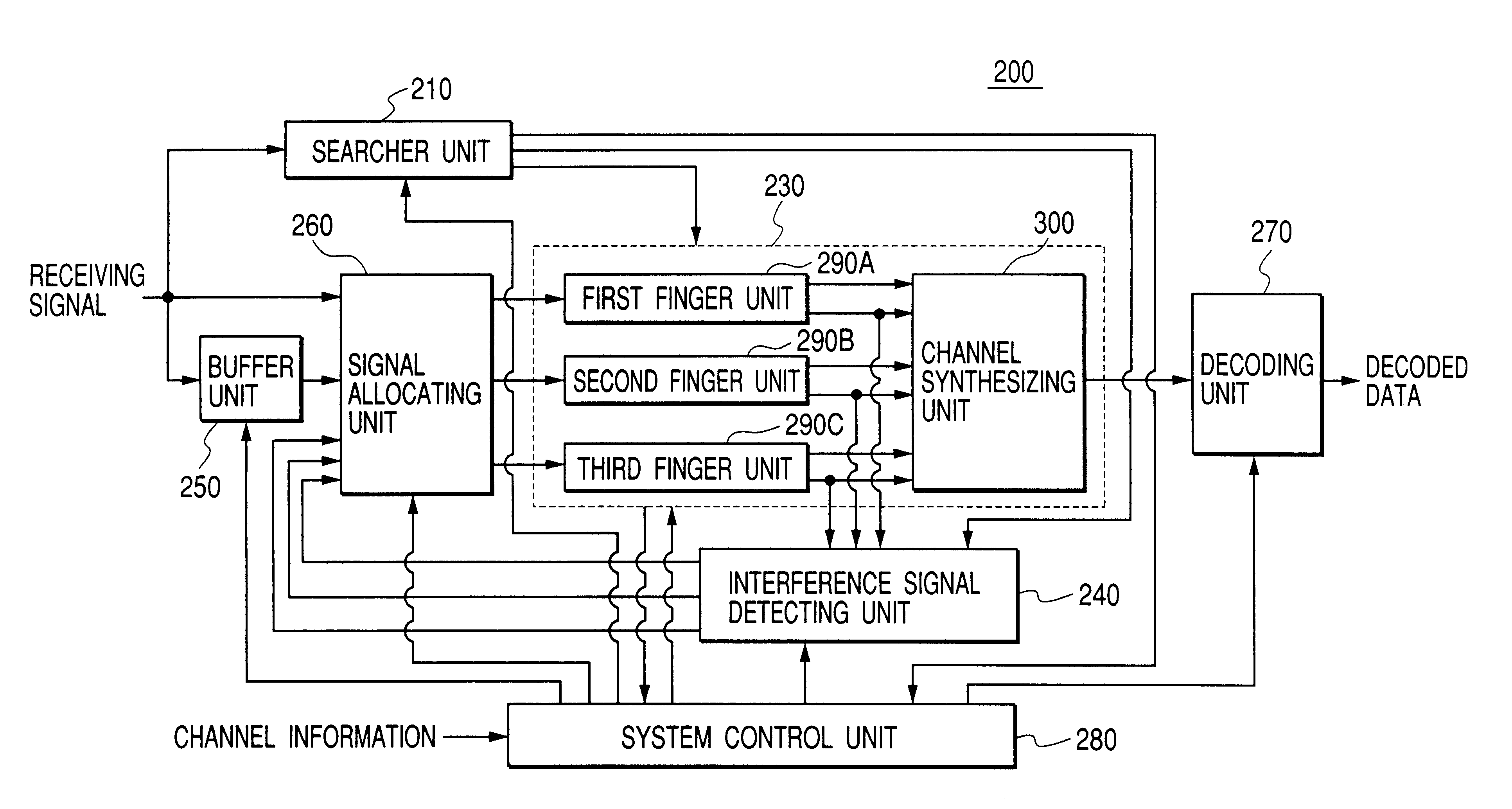
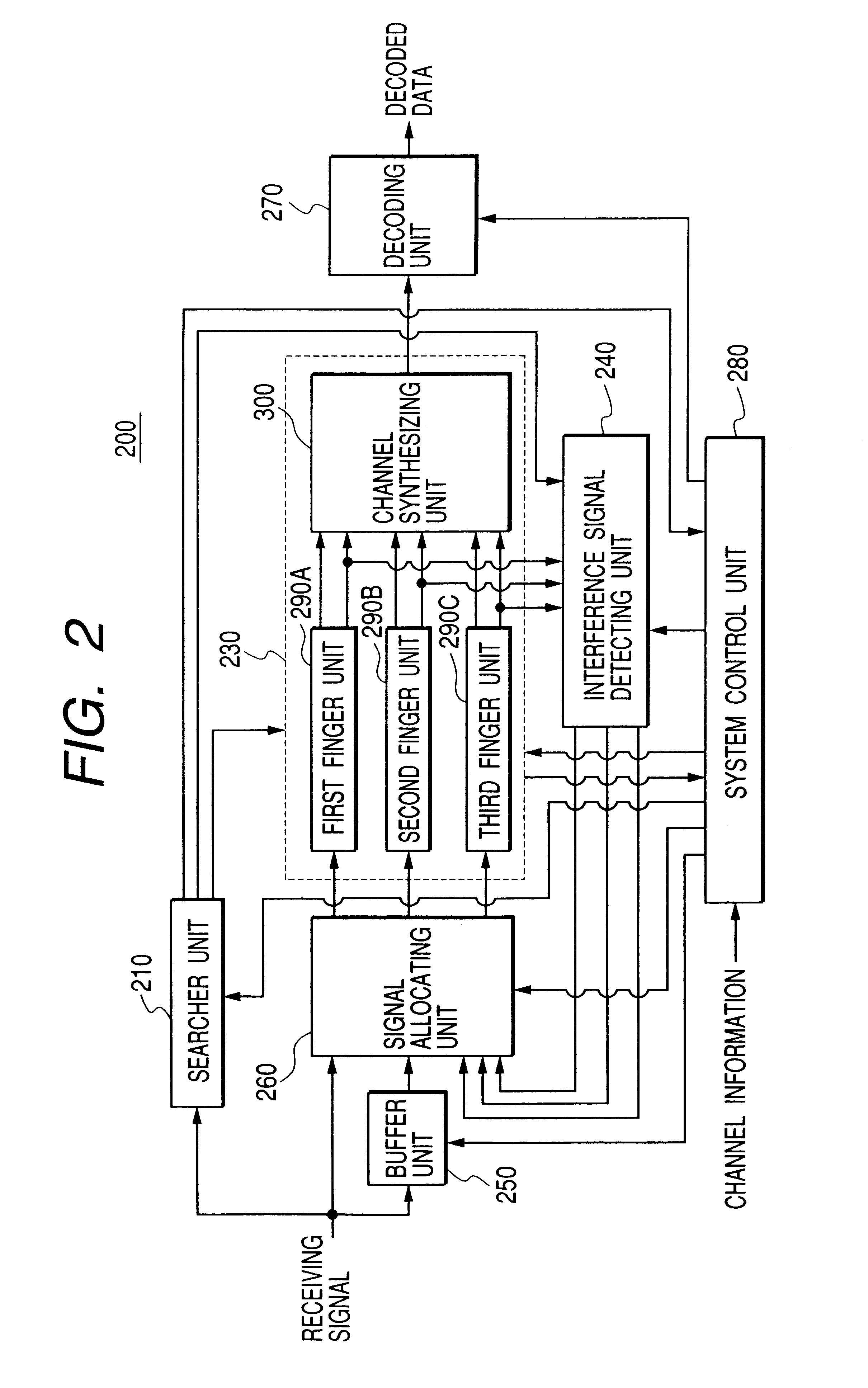
In this embodiment, pieces of transmission data transmitted at various processing gains (corresponding to various symbol time periods) from the spread spectrum signal transmitting apparatus 100 are received in a spread spectrum signal receiving apparatus, and each piece of transmission data transmitted at one processing gain is demodulated in a corresponding finger unit of the receiving apparatus while holding a synchronization with the transmission data in a low signal electric power Eb / No environment and performing a phase detection for the transmission data in a synchronized condition. Three examples of a transmission data format of the pieces of transmission data planned to be demodulated in the finger units are shown in FIG. 11A, FIG. 11B and FIG. 11C.

FIG. 11A shows an example of a transmission data format in which three pieces of transmission data of the same low processing gain (or the same data rate) corresponding to three data channels (that is, three cod...

third embodiment

FIG. 20 is a block diagram of a spread spectrum signal transmitting apparatus of a spread spectrum communication apparatus according to the present invention.

As shown in FIG. 20, a spread spectrum signal transmitting apparatus 500 comprises:

an input data selector 501 for receiving format information and a plurality of strings of input data respectively corresponding to a data transfer rate (or a data speed), a communication quality and an importance degree and selecting each input data string according to the format information;

a data transmitting unit 502, corresponding to a plurality of code channels, for transforming one input data string selected by the input data selector 501 for each code channel to produce a string of transmission data, generating a pilot signal, transforming the pilot signal, transmitting the strings of transmission data through the code channels and transmitting the pilot signal through a pilot channel allocated as one code channel;

a multiplexing unit 503 f...


PUM


Abstract

A searcher detecting signal indicating conditions of propagation paths is detected from incoming waves of a pilot signal transmitted at the highest electric power. In a RAKE reception for one code channel, an interference replica signal functioning as an interference signal for an incoming wave of the code channel to be demodulated in one finger unit is produced from reference signals produced in the other finger units and the searcher detecting signal, an interference removal is performed for a receiving signal according to the interference replica signal, and the demodulation of the RAKE reception is performed. In the demodulation based on a plural code channel, a reference signal is produced in one of the finger units, an interference replica signal is produced from the reference signal and the searcher detecting signal, an interference removal is performed for the receiving signal according to the interference replica signal, and the demodulation based on the plural code channel is performed. Accordingly, a service of a high speed data transmission can be performed without increasing an occupied band as well as a service mainly performing a low speed data transmission.

Description

BACKGROUND OF THE INVENTION1. Field of the InventionThe present invention relates to a spread spectrum communication apparatus in which a spread spectrum signal obtained by performing a code division multiplex with orthogonal codes for transmission data is transmitted and the spread spectrum signal is received to reproduce the transmission data.2. Description of the Related ArtTo transmit data of a plurality of channels, a division multiplex is generally performed for the data. As a method of the division multiplex, a frequency division multiplex (FDM) method, a time division multiplex (TDM) method and a code division multiplex (CDM) method are well-known.In the CDM method, a time-frequency-power space, in which orthogonal codes are spread, is divided into a plurality of sub-spaces corresponding to code channels along the power axis, an orthogonal transformation for data of each code channel is performed by using an orthogonal code spreading within one limited power zone of the time...

Claims


Application Information

Patent Timeline
Patent Type & Authority Patents(United States)
IPC IPC(8): H04B1/707
CPCH04B1/70735H04B1/7117H04B1/7107H04B1/7115
Inventor IWAKIRI, NAOHIKO
Owner SONY CORP
Learn More