Surface working device and attachable protector

a working device and protector technology, applied in the direction of mechanical machines/dredgers, roads, construction, etc., can solve problems such as problems, and achieve the effect of reducing the likelihood of bolt shear and good protection

Inactive Publication Date: 2004-10-05
SANDVIK INTELLECTUAL PROPERTY AB
View PDF17 Cites 21 Cited by
  • Summary
  • Abstract
  • Description
  • Claims
  • Application Information

AI Technical Summary

Benefits of technology

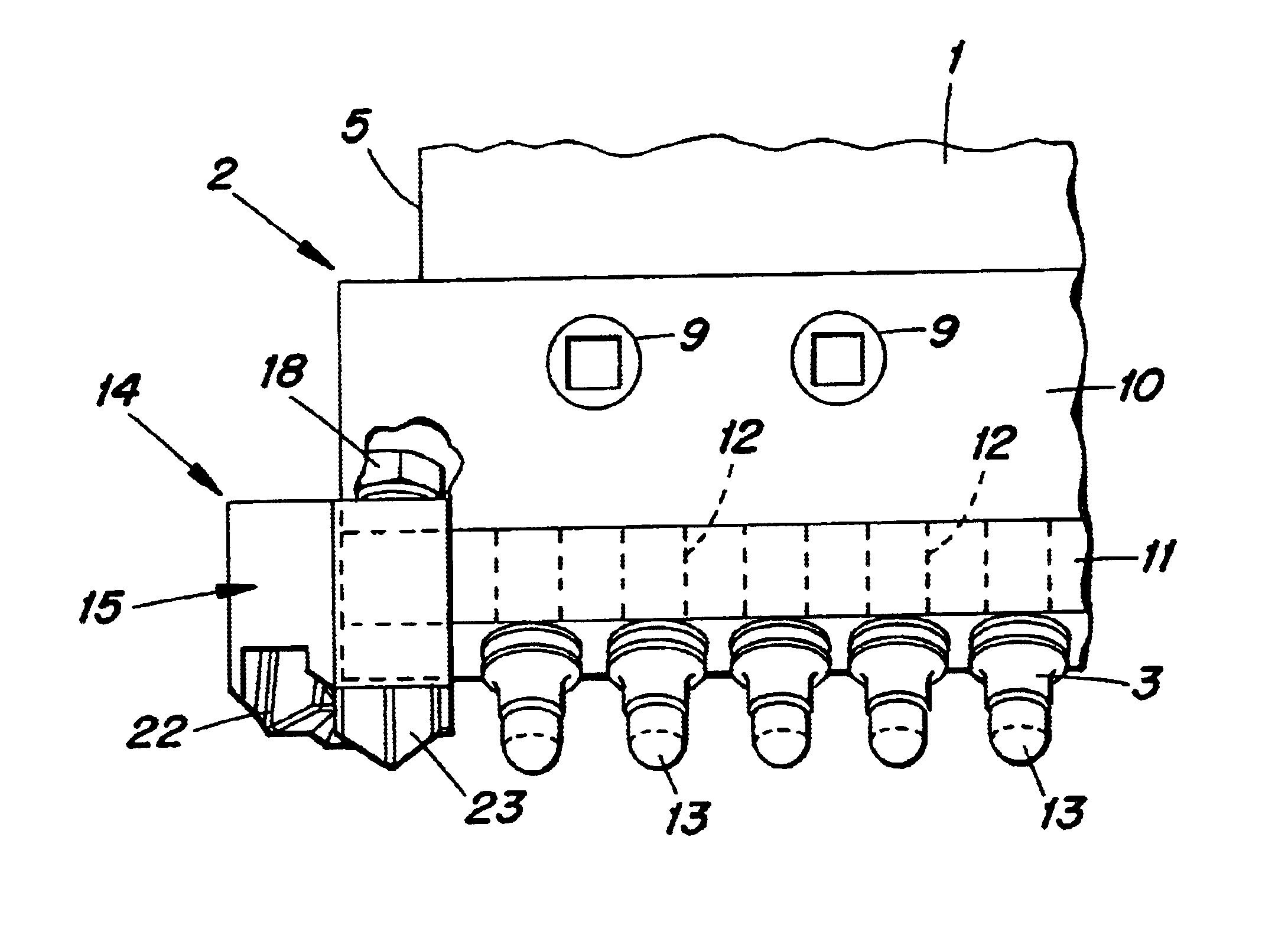
The use of one or more of the pick holes to mount the end protector in place provides a secure attachment that resists riding up of the end protector. Furthermore, the orientation of the bolt or other fastener within the pick hole helps to reduce the likelihood of bolt shear or the like.
An end protector attached in accordance with the present invention may provide good protection for the working element when for example it is used in the working of hard surfaces, such as compacted dirt tracks and the like, and may also be used, e.g., in mining board systems for, e.g., open cut mines, quarries and hard rock mines. It may also however be used with working elements in general across the range of working applications, such as ice and snow clearing and the like.
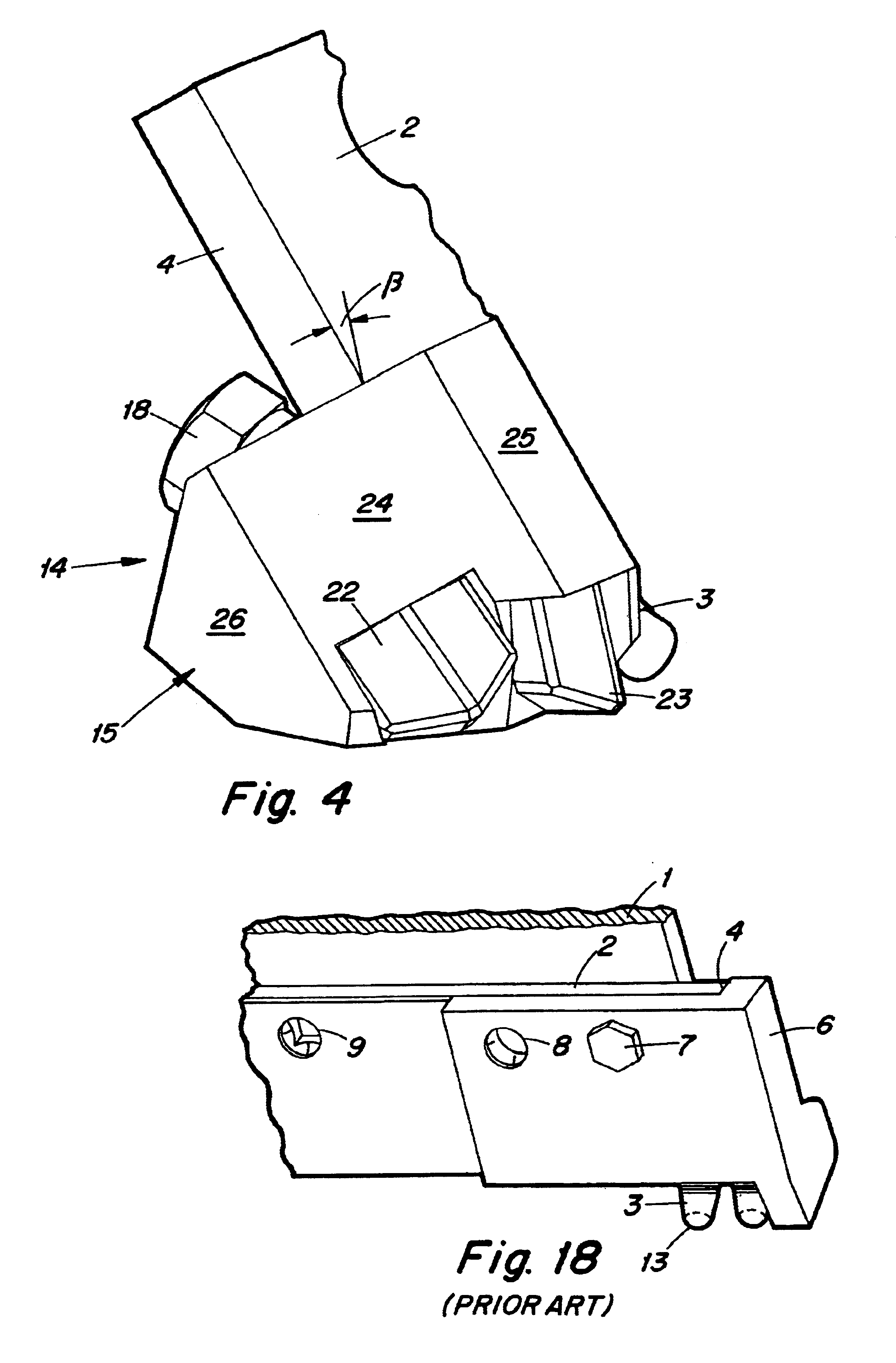
The end protector may include more than one protective surface, so that for example one surface provides more protection when the working blade is oriented in one direction, e.g., angled more towards the direction of travel of the grading vehicle, whilst another surface provides more protection when the working blade is oriented in another direction, e.g., angled more transversely with regard to the direction of movement of the grading vehicle. For example, one surface may provide (the main) protection between about 20.degree. and about 45.degree., whilst another may provide (the main) protection between about 45.degree. and about 90.degree..
These tool portions may also provide protection to the leading edge of the working element, e.g., when the working element is in a more transverse orientation with respect to vehicle advance.
In all of the above, the mounting of the end protector in a pick hole of the working element has the further advantages that the end protector can be easily removed and replaced, and that the end protector can be retrofitted to existing blade assemblies.

Problems solved by technology

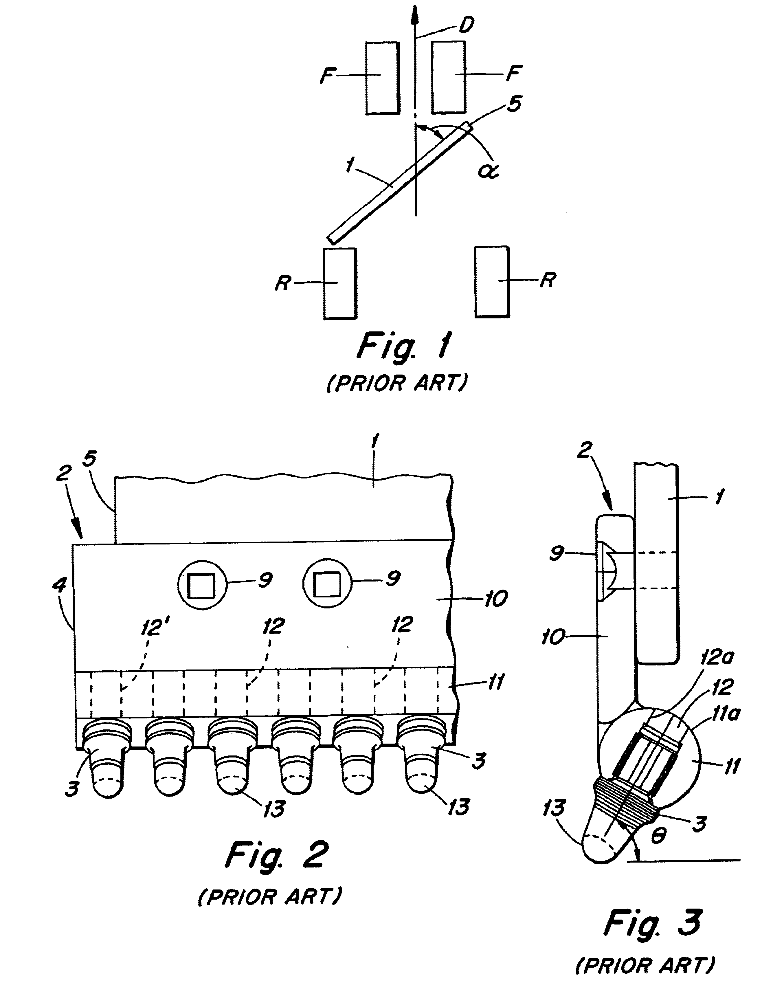
The inventors of the present invention have found, however, that problems can occur when the blade 1 is used to grade or plane hard road surfaces, such as are often found on dirt roads and country tracks.

Method used


Image

  • Surface working device and attachable protector
  • Surface working device and attachable protector
  • Surface working device and attachable protector

Examples


second embodiment

An alternative manner of obtaining an engagement of the working element and the end protector is provided in the present invention, as shown in FIG. 6.

first embodiment

As can be seen, the protector 14' of this embodiment is similar to that of the first embodiment, although in this case the protector 14' is designed to fit onto the opposite end of the cutter board 2 from that of the previous embodiment. Thus, it would be used when the blade 1 of FIG. 1 is arranged to face to the right.

In this embodiment, the bolt 18 is replaced by a fastening element 27 having a stepped configuration. Thus, the fastening element 27 has a shank portion 28 of a diameter that allows it to pass through the pick holes 12, and a head portion 29 that is of larger diameter than the shank portion 28 and also is of a larger diameter than the pick holes 12 at their top opening 12a. The fastening element 27 also has a stepped portion 30 as a transition between the shank portion 28 and head portion 29.

The head portion 29 is threaded, and engages a threaded hole 31 in the top face 19 of the end protector 14'. The shank portion 28 is unthreaded, and extends into a recess 32 in th...


PUM


Abstract

An end protector for a working element of a road grading machine or the like. The working element includes a body portion having a plurality of holes therein for holding picks that work a road surface. The end protector is held in place through the use of a vacant pick hole of the working element by a fastening element that extends through the hole.

Description

The application claims priority under 35 U.S.C. .sctn..sctn.119 and / or Patent Application Serial No. PR8512 filed in Australia on Oct. 26, 2001, the entire content of which is hereby incorporated by reference.The present invention relates to a surface working device, such as for planing and grading roads, and to an attachable protector for the same.Various road maintenance systems exist for working road surfaces. Such working may for example take the form of grading and planing a road, e.g., in order to provide a dirt road or the like with a smooth driving surface. It could also take the form of for example ice and snow scraping for keeping roads open in winter conditions, as well as asphalt planing and gravel maintenance.As shown in FIG. 1, such systems typically include a planing blade 1 which breaks up and smooths the surface of a road. The blade 1 is mounted beneath a vehicle between the vehicle's front and rear wheels F and R.The planing blade 1 is generally angled to the direc...

Claims


Application Information

Patent Timeline
Patent Type & Authority Patents(United States)
IPC IPC(8): E02F3/76E02F3/815
CPCE02F3/8157
Inventor WEAVER, STEVENMCLEAN, MICHAEL ANDREWTRUEBODY, MARK JAMES
Owner SANDVIK INTELLECTUAL PROPERTY AB
Why Eureka
Try Eureka