Method for making a microstructure in a glass or plastic substrate according to hot-forming technology and associated forming tool

a technology of hot-forming technology and micro-structure, which is applied in the direction of glass making apparatus, dough shaping, glass shaping apparatus, etc., can solve the problems of affecting the quality of the formed structure, and requiring a considerable amount of effor

Inactive Publication Date: 2004-10-05
SCHOTT AG
View PDF19 Cites 37 Cited by
  • Summary
  • Abstract
  • Description
  • Claims
  • Application Information

AI Technical Summary

Benefits of technology

It is an object of the present invention to provide a method of making a microstructure in a glass or plastic substrate of the above-described type, in which the negatively structured surface of the forming tool fills with melted glass or plastic as completely as possible during formation of the microstructure with the forming tool, and in which the formed structure is not damaged when the forming tool is removed from the substrate.

Problems solved by technology

The problems with other engineering applications are similar.
This process requires a considerable effort and is expensive.
On the other hand, the glass or the plastic to be structured must be able to separate again from the forming tool material after formation of the desired .mu.m-scale structure i.e. the wetting should thus be poor.
In practice materials that have very good wetting behavior produce good .mu.m-scale structures, but the adhesion experienced during separation causes breakage of the formed structures.
The required .mu.m-geometry of the formed structures is poor when the wetting of the materials is poor.
Up to now it has not been possible to find a combination of materials, which satisfy the above-described requirements in an optimum manner, i.e. that is which guarantee that the negatively structured surface on the forming tool is completely filled when the forming tool is pressed into the substrate and that the structure produced is not broken when the forming tool is withdrawn from the structure, i.e. on shaping of the structure.

Method used


Image

  • Method for making a microstructure in a glass or plastic substrate according to hot-forming technology and associated forming tool
  • Method for making a microstructure in a glass or plastic substrate according to hot-forming technology and associated forming tool
  • Method for making a microstructure in a glass or plastic substrate according to hot-forming technology and associated forming tool

Examples


Embodiment Construction

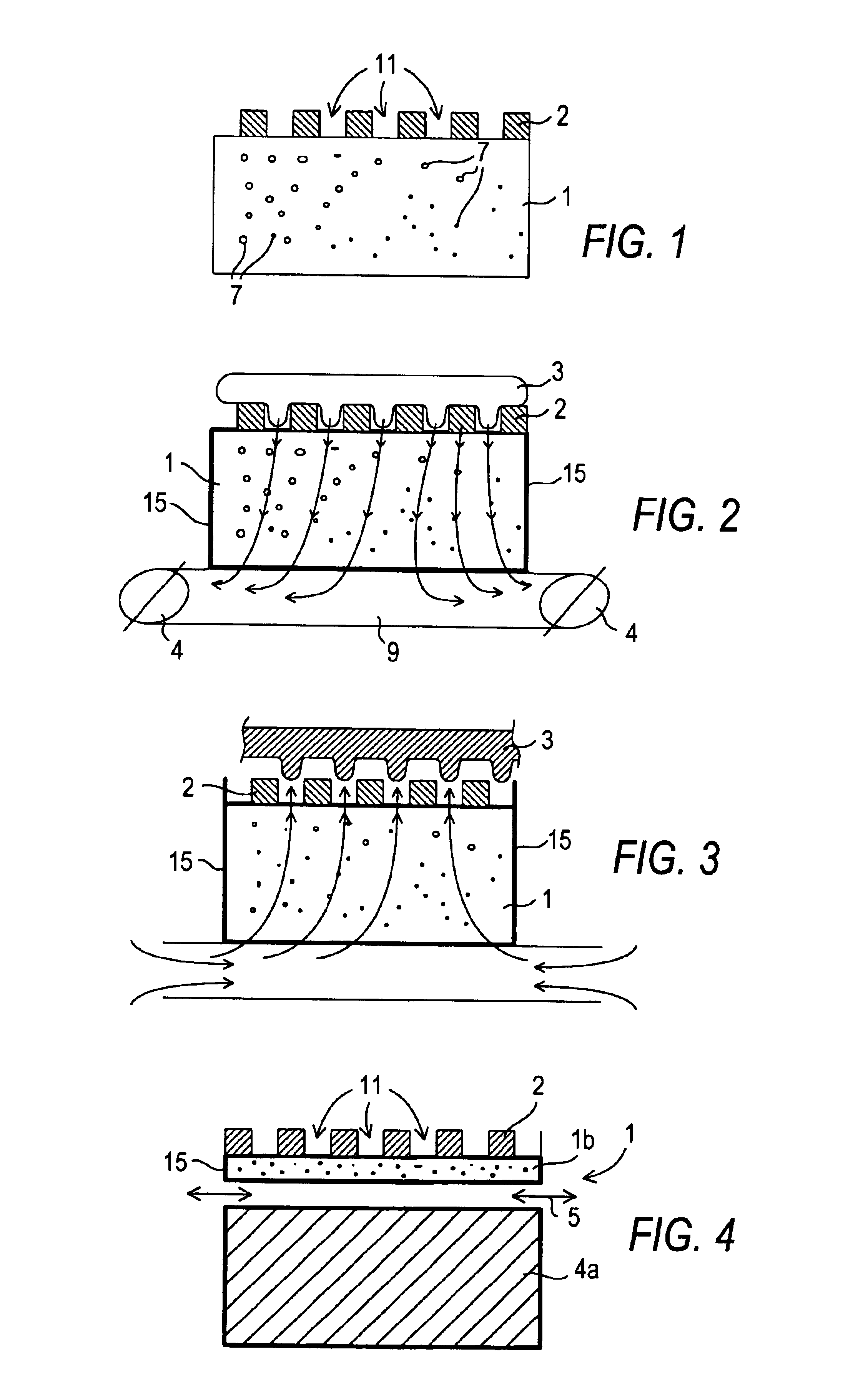
The basic structure of the forming tool according to the invention is shown in the cross-sectional view provided in FIG. 1. The embodiment of the forming tool shown in FIG. 1 comprises a base body 1 made of a porous base material provided with an open pore structure comprising a plurality of open pores 7, so that the base body 1 is air-permeable or gas-permeable. This open pore structure can be provided e.g. by a sintering process. The porous base material can be metallic or preferably ceramic in nature.

The principle different forming tool shapes used in the method are not shown. Rotationally symmetric rolls and planar pressing tools, dies or molds are typically used in this type of hot forming method. Only the positioning / clamping of the forming tool for the structuring is adjusted to their form.

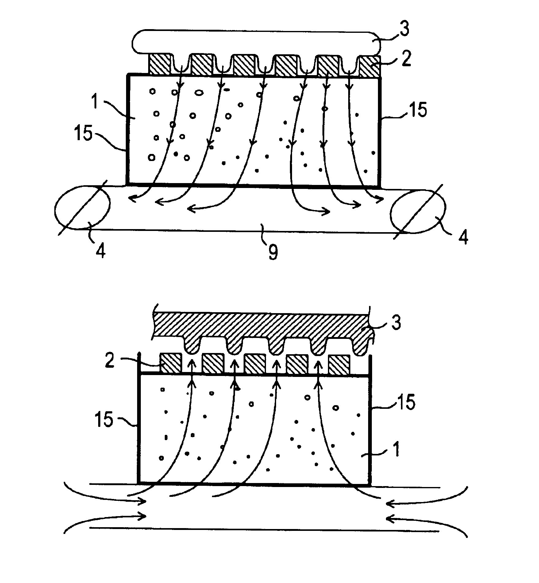
The operative layer 2, i.e. the structured surface of the forming tool, is applied to the base body 1. The operative layer 2 is not porous or does not have an open pore structure. The struc...


PUM

PropertyMeasurementUnit
widthaaaaaaaaaa
lengthaaaaaaaaaa
widthaaaaaaaaaa

Abstract

A microstructure is formed in a viscous glass or plastic substrate by pressing a structured surface of a forming tool corresponding to a negative of the microstructure to be produced in the viscous glass or plastic substrate. After the microstructure has been formed, the forming tool is removed from the surface. In order to help form the microstructure and remove the forming tool from the substrate the forming tool has an at least partially porous base body (1) and an operative layer (2) structured with a negative structure consisting of grooves (11) extending to the porous base body (1). The forming of the microstructure in the substrate is assisted by applying suction to the porous base body (1) so that the grooves (11) fill more easily and completely with melted glass or plastic material. The removal of the forming tool after forming the microstructure is assisted by applying an overpressure to the porous body to help release the solidified glass or plastic material from the forming tool.

Description

BACKGROUND OF THE INVENTION1. Field of the InventionThe present invention relates to a method of making a microstructure in a glass or plastic substrate according to hot-forming or hot-shaping technology, in which the microstructure is formed in viscous glass or plastic by pressing a forming tool, whose surface is structured according to a negative of the microstructure to be made, into the glass or plastic substrate and then removing the forming tool from it after completing the structuring. The invention also relates to the forming tool used to make this sort of microstructure according to hot-forming technology.2. Related ArtGlass or plastic substrates, whose surfaces have a microstructure, are required in certain new engineering fields. For example, plate glass for precision applications provided with a microstructure of even higher precision is employed, especially in display devices, illuminating systems and in optical and medical engineering applications and in sensor technol...

Claims


Application Information

Patent Timeline
Patent Type & Authority Patents(United States)
IPC IPC(8): B29C59/02C03B11/06C03B9/00C03B13/16C03B11/08C03B23/035C03B23/02C03B13/00C03B13/14C03B11/00H01J9/02H01J17/16
CPCB29C59/02C03B9/00C03B11/082C03B13/14C03B13/16C03B23/0352C03B11/08B29C2059/023B29C2791/006C03B2215/413
Inventor HERZBACH, LARS CHRISTIANTHIEL, STEFFENPOSTRACH, STEFAN
Owner SCHOTT AG
Why Eureka
Try Eureka