Liquid crystal display device

a liquid crystal display and display device technology, applied in the direction of instruments, polarising elements, chemistry apparatus and processes, etc., can solve the problems of reducing display quality, high cost, and undesirable to provide reflectors, and achieves high contrast, substantial white display, and high quality

Inactive Publication Date: 2004-10-05
MITSUBISHI ELECTRIC CORP
View PDF7 Cites 159 Cited by
  • Summary
  • Abstract
  • Description
  • Claims
  • Application Information

AI Technical Summary

Benefits of technology

The present invention has been accomplished to solve the above problems and an object of the present invention is thus to provide a liquid crystal display device having a reflective liquid crystal display element presenting high quality images with high contrast and substantially white display.

Problems solved by technology

However, the transmissive type has the problem of dim display in bright ambient light, and the reflective type has the problem of dark display in low ambient light.
It significantly decreases display quality, causing such a problem that black does not appear real black due to the surface reflected light.
For the same reason, it is also undesirable to provide the reflector 31 outside of the substrate 21b.
Though the use of multi-domain technique allows separate twist angle setting for the transmissive section and reflective section, it costs a lot and therefore the same setting is generally applied.
However, the half wave retarder is generally provided in spite of the disadvantages of higher thickness and costs since it achieves high contrast images.
Therefore, when using a circular polarizer having a composite structure consisting of a half wave retarder and quarter wave retarder, an actual driving voltage of 5V or below does not provide sufficient darkness in a black display, thus reducing contrast.
However, the above prior art does not specify a display color.
Therefore, when it appears yellow with the C light source, it appears the same under normal use conditions, which is of a problem.
Since the problem that a white display in the reflective section turns yellow occurs under the conditions in the reflective section only, the same problem occurs in a reflective liquid crystal display device using the reflective display element only, and a transflective liquid crystal display device.

Method used


Image

  • Liquid crystal display device
  • Liquid crystal display device
  • Liquid crystal display device

Examples


first embodiment

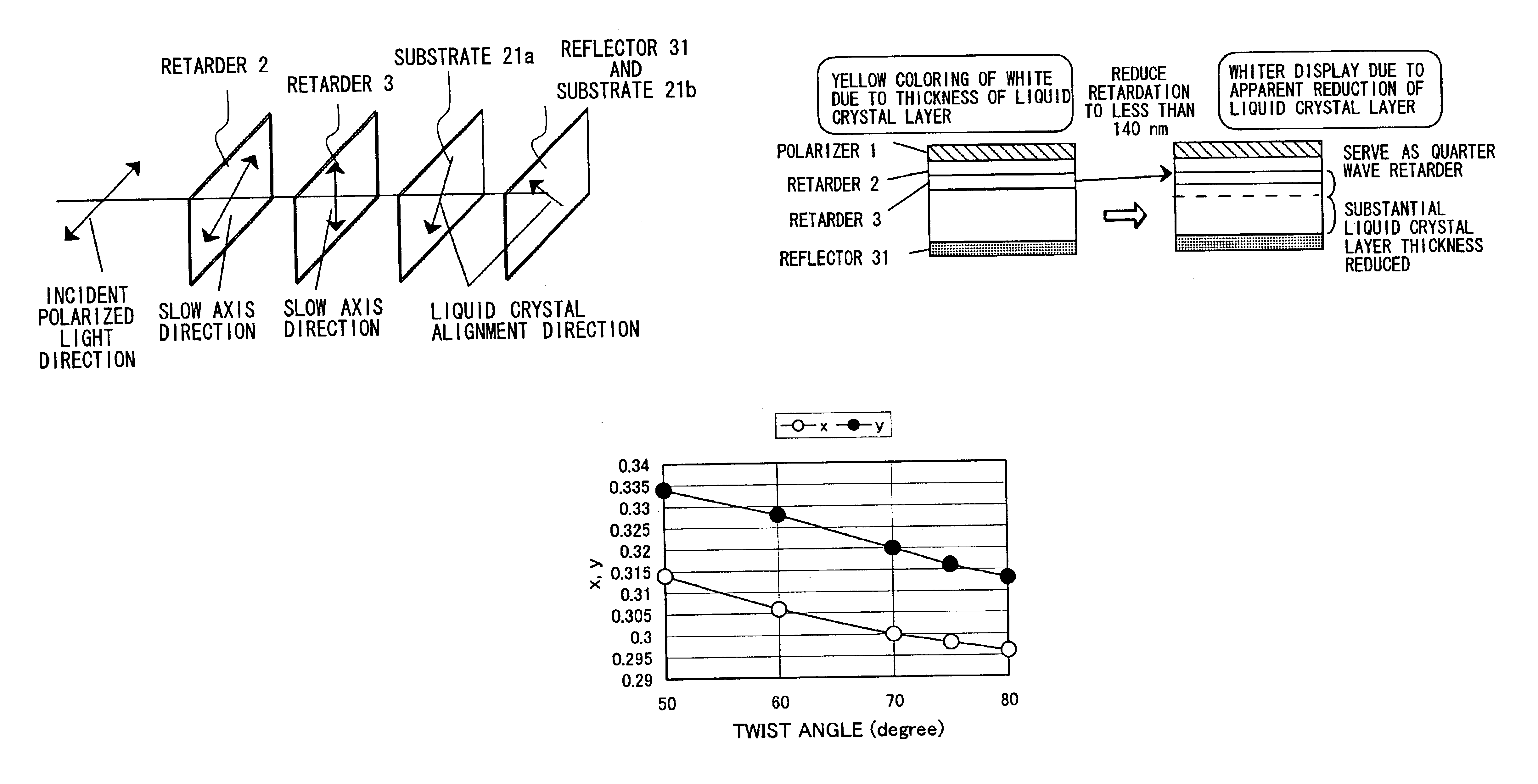
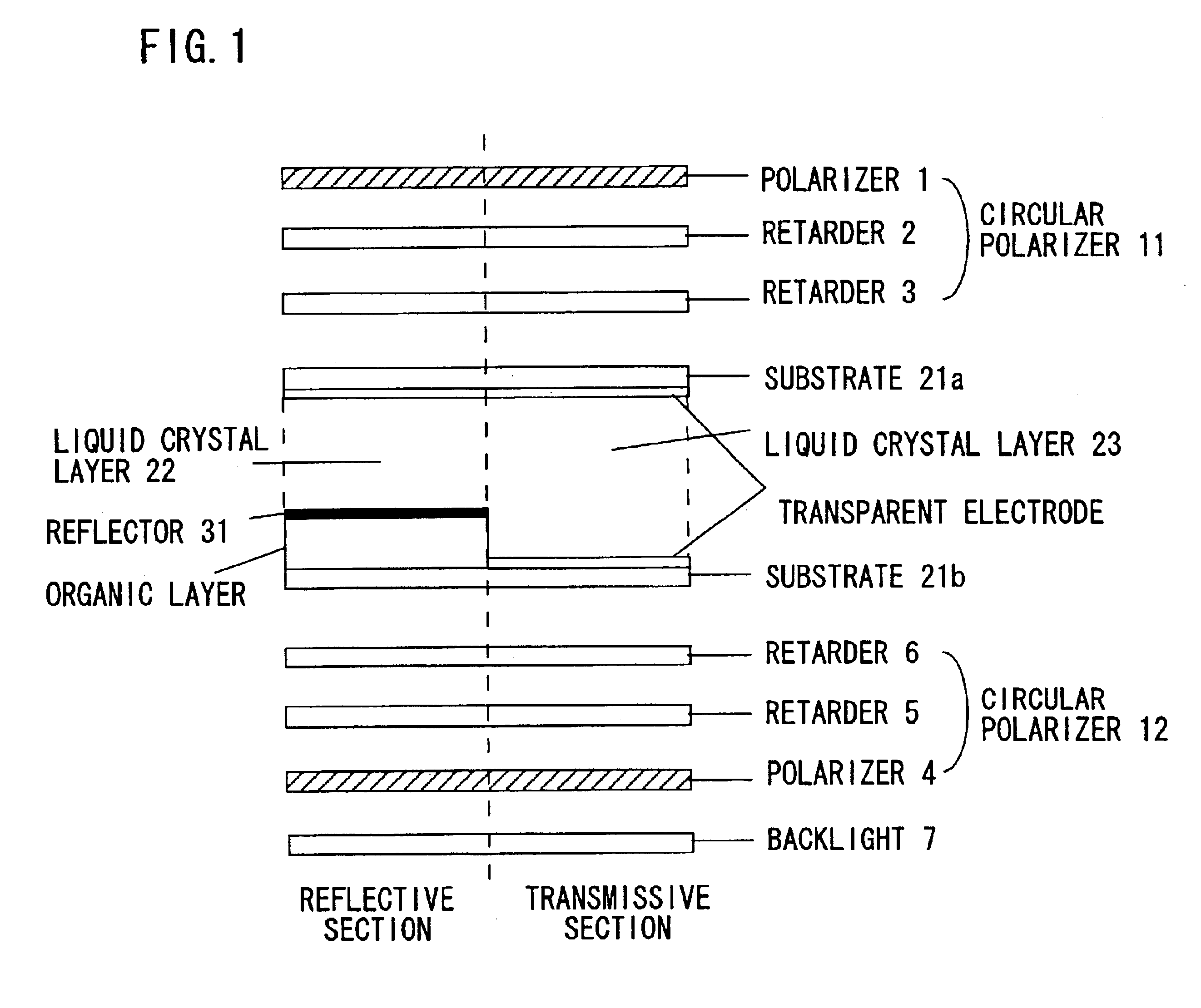
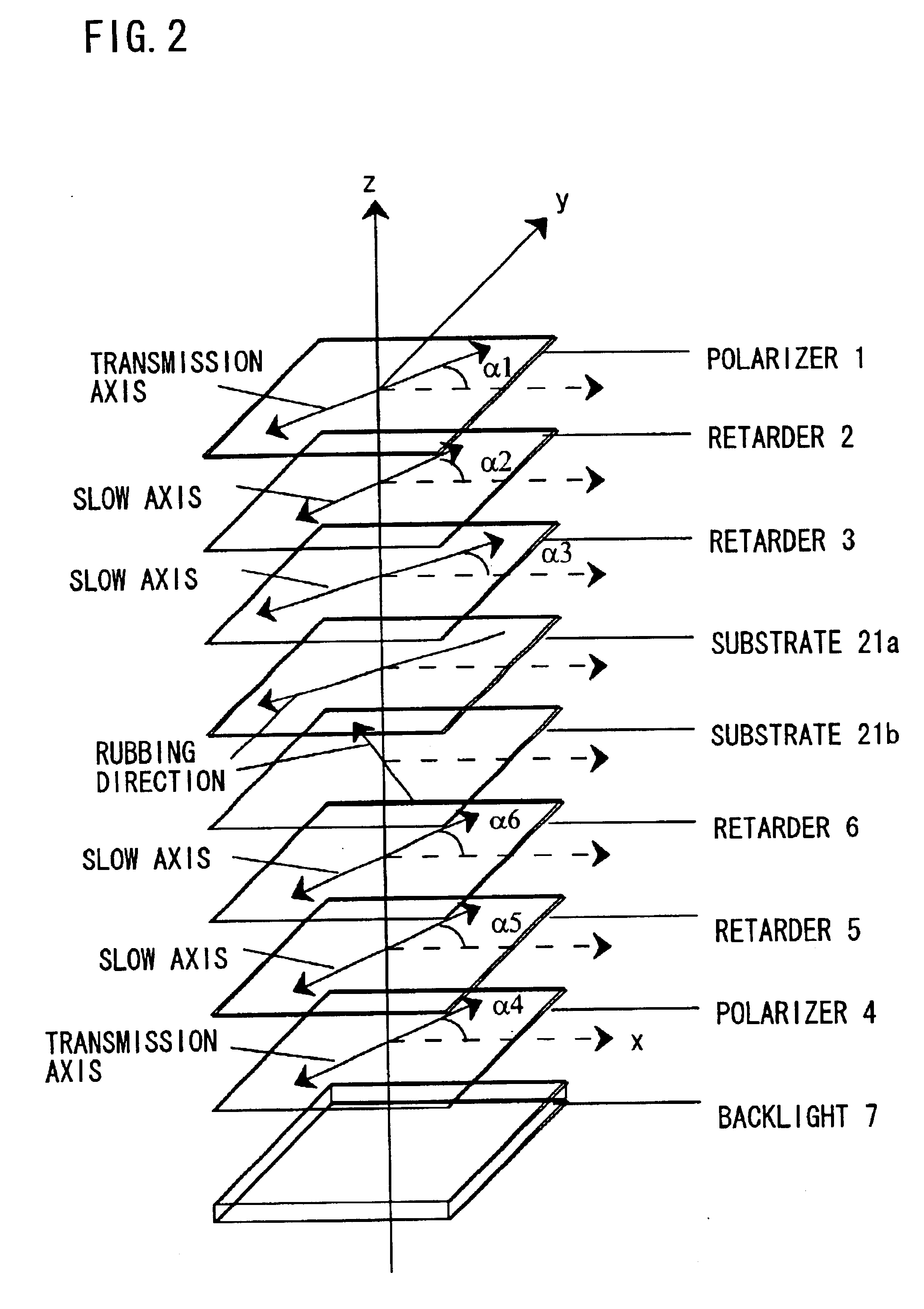
Table 2 shows a configuration example of a transflective liquid crystal display device according to the present invention. The symbols referring angles in Table 2 are shown in FIG. 2. .DELTA.nd of the liquid crystal layer 22 in the reflective section is 167 nm, .DELTA.nd of the liquid crystal layer 23 in the transmissive section is 288 nm, a twist angle is -70 degrees, and a rubbing direction at the side of the transparent substrate 21a is 235 degrees. The bisector of alignment directions of liquid crystal material at substrate interfaces is in the direction of 90 degrees.

TABLE 2 Polarizer 1 .alpha.1 = 22 degrees Retarder 2 .alpha.2 = 33 degrees, retardation 280 nm Retarder 3 .alpha.3 = 89 degrees, retardation 135 nm Polarizer 4 .alpha.4 = 100 degrees Retarder 5 .alpha.5 = 168 degrees, retardation 275 nm Retarder 6 .alpha.6 = 283 degrees, retardation 125 nm

The optical properties of the reflective and transmissive sections in the transflective liquid crystal display device according ...

second embodiment

Table 3 shows another configuration example of a transflective liquid crystal display device according to the present invention. The symbols referring angles in Table 3 are shown in FIG. 2..DELTA.nd of the liquid crystal layer 22 in the reflective section is 174 nm, .DELTA.nd of the liquid crystal layer 23 in the transmissive section is 294 nm, a twist angle is -66 degrees, and a rubbing direction at the side of the transparent substrate 21a is 240 degrees. The bisector of alignment directions of liquid crystal material at substrate interfaces is in the direction of 93 degrees. A hybrid alignment liquid crystal film (NHfilm, Nippon Oil Corporation) is used for the retarder 6.

TABLE 3 Polarizer 1 .alpha.1 = 20 degrees Retarder 2 .alpha.2 = 36 degrees, retardation 260 nm Retarder 3 .alpha.3 = 96 degrees, retardation 120 nm Polarizer 4 .alpha.4 = 95 degrees Retarder 5 .alpha.5 = 161 degrees, retardation 285 nm Retarder 6 .alpha.6 = 272 degrees, retardation 130 nm

The liquid crystal displ...


PUM

PropertyMeasurementUnit
thicknessaaaaaaaaaa
twist angleaaaaaaaaaa
angleaaaaaaaaaa

Abstract

A liquid crystal display device has an elliptic polarizer consisting of a polarizer, a first retarder, and a second retarder, and a reflector reflecting light in a visual light range. Optimal values for a twist angle of a liquid crystal layer, an angle between a transmission axis of the polarizer and a slow axis of the first retarder, an angle between the slow axis of the first retarder and a slow axis of the second retarder, and a product of birefringence .DELTA.n of liquid crystal material used in the liquid crystal layer and a thickness d of the liquid crystal layer are evaluated.

Description

BACKGROUND OF THE INVENTION1. Field of the InventionThe present invention relates to a liquid crystal display device having a reflective liquid crystal display element, such as a reflective liquid crystal display device and a transflective liquid crystal display device including a reflective liquid crystal display element and a transmissive liquid crystal display element.2. Description of Related ArtBeing thin, lightweight, and low power consumption, a liquid crystal display device is widely used as a portable device display. Since the liquid crystal display device is not a light emitting element, it requires an external light source. Depending on the type of the external light source, the liquid crystal display device is divided roughly into two categories: transmissive-type and reflective-type.A transmissive liquid crystal display device has a backlight using an light emitting element such as a cold-cathode fluorescent lamp and LED mounted behind the device, that is, the opposite ...

Claims


Application Information

Patent Timeline
Patent Type & Authority Patents(United States)
IPC IPC(8): G02F1/13G02F1/1335G02B5/30G02F1/13363G02F1/139
CPCG02F1/133555G02F1/13363G02F2001/133541G02F2413/08G02F2202/40G02F2203/02G02F2413/04G02F2001/1398G02F1/133541G02F1/1398
Inventor KOYAMA, HITOSHIKURATA, TETSUYUKISATAKE, TETSUYANISHIOKA, TAKAHIRO
Owner MITSUBISHI ELECTRIC CORP
Why Eureka
Try Eureka