Focus control system

a control system and focus technology, applied in the field of manufacturing processes, can solve the problems of deviating from the optimal focus, insufficient focus control in itself, and insufficient closed-loop dose, etc., and achieve the effect of reducing the amount of focusing

Inactive Publication Date: 2004-10-12
GLOBALFOUNDRIES INC
View PDF24 Cites 32 Cited by
  • Summary
  • Abstract
  • Description
  • Claims
  • Application Information

AI Technical Summary

Problems solved by technology

Some of these types of targets use image shortening effects to make the visual measurements even though the individual array elements are not resolvable.
The problem remains, however, of providing a control system to feed back focus corrections to the lithography tool.
The mere ability to determine that dose and / or focus is deviated from optimum is not sufficient in itself for closed-loop dose and focus control.
For the most part, the prior art does not fully address 1) the need to determine both the sign and magnitude of a focus correction feedback to maintain an imaging system at optimum focus, 2) the need for adequate sensitivity to small defocus deviations from an optimum focus position, 3) the need to decouple and distinguish dose and focus variation, 4) the need for automated measurement and feedback.

Method used


Image

  • Focus control system
  • Focus control system
  • Focus control system

Examples


Embodiment Construction

)

In describing the preferred embodiment of the present invention, reference will be made herein to FIGS. 1 through 6 of the drawings in which like numerals refer to like features of the invention. Features of the invention are not necessarily shown to scale in the drawings.

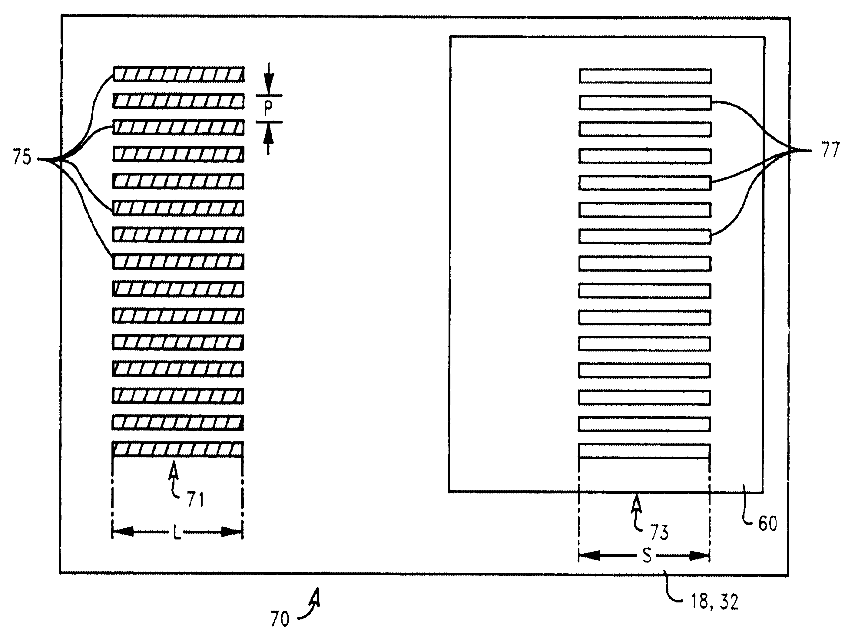
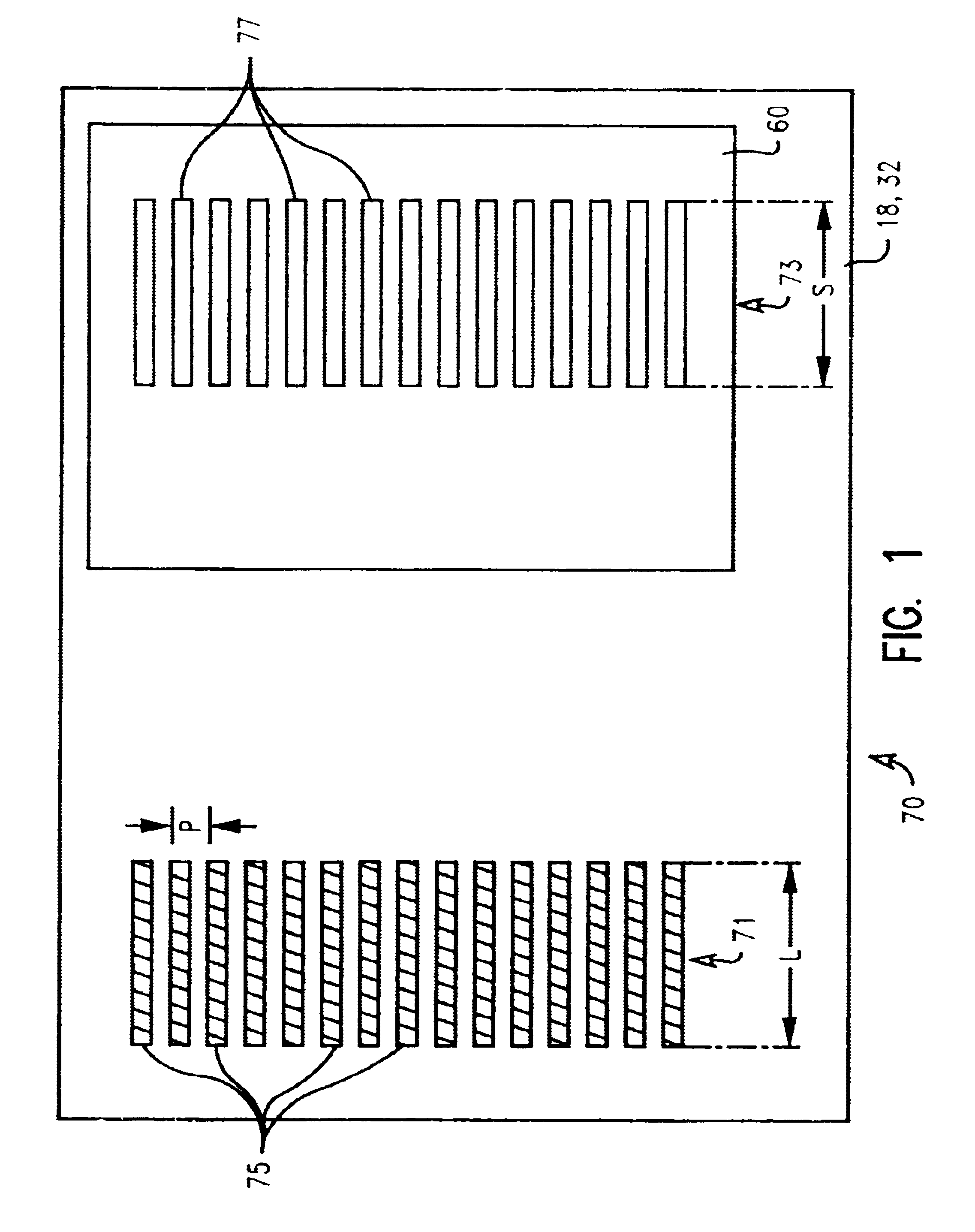
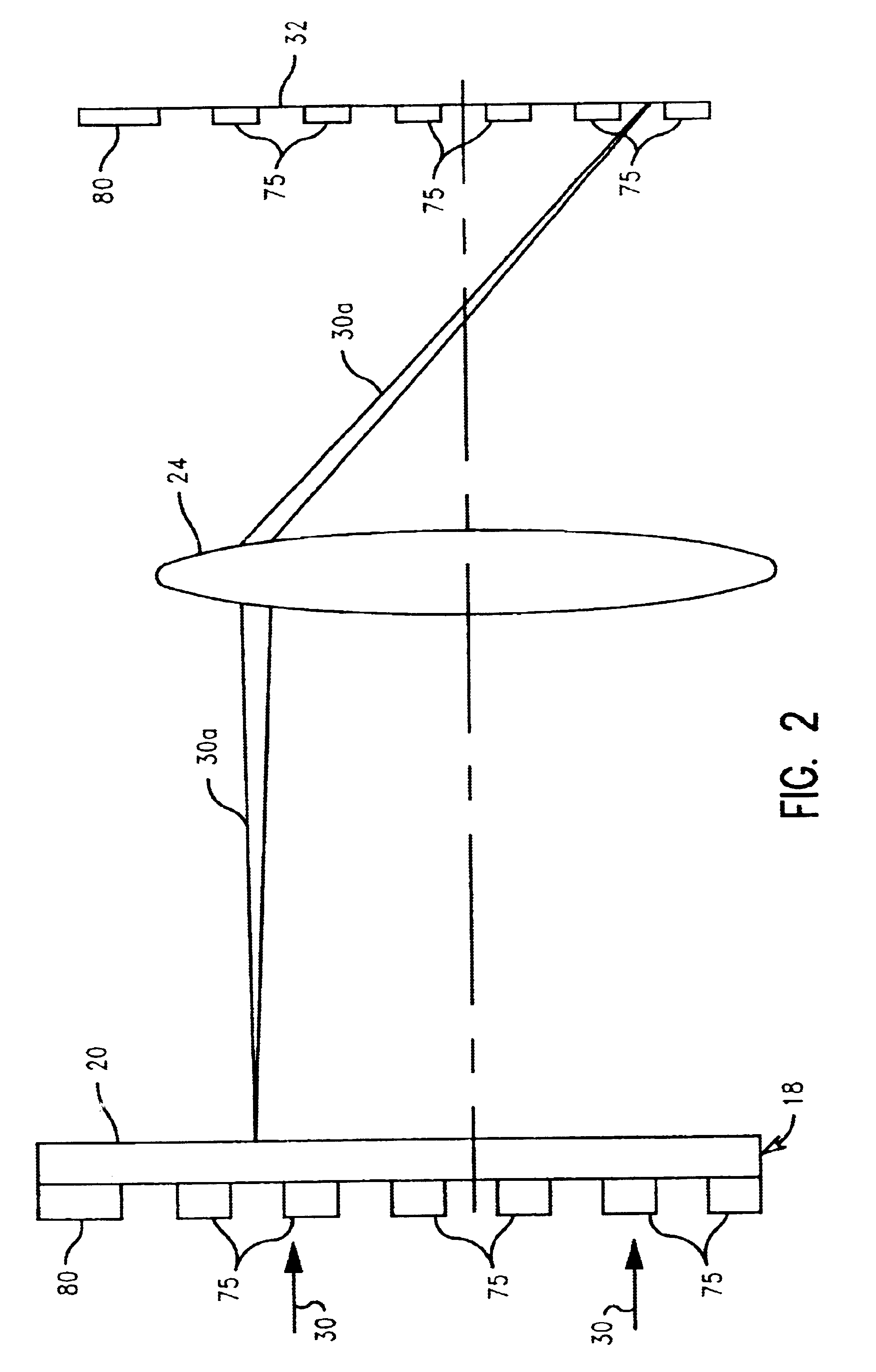
The present invention provides a method and system of controlling focus of the energy beam used in the lithographic process. Such a focus control system is particularly useful because it knows both the sign and magnitude of defocus in order to provide feed back focus corrections to the lithography tool.

Initially, the method places one or more measurable targets within the area of the product reticle that is exposed simultaneously with chip patterns. The arrangement of targets can be tailored to spatial components of focus variation; such as across field tilt and curvature. The process then exposes a selected field or fields at focus offsets relative to the remainder of the fields on the product wafer, where the of...


PUM

PropertyMeasurementUnit
energyaaaaaaaaaa
lengthaaaaaaaaaa
widthaaaaaaaaaa

Abstract

A process for controlling focus parameters in a lithographic process used in manufacture of microelectronic circuits. The process comprises initially providing a lithographic mask having a target mask portion containing a measurable dimension sensitive to defocus, projecting an energy beam through the target mask portion onto a first location of a substrate at a first focus setting, and lithographically forming a first target on the substrate corresponding to the first focus setting, the first target containing a measurable dimension sensitive to defocus. The process then includes projecting an energy beam through the target mask portion onto a second location of the substrate at a second focus setting, lithographically forming a second target on the substrate corresponding to the second focus setting, the second target containing a measurable dimension sensitive to defocus, and measuring the defocus sensitive dimension for each of the first and second targets on the substrate. The defocus sensitive dimension of the first and second targets are then compared and there is determined a desired focus setting of the energy beam based on the comparison of the dimensions of the first and second target. The process may be used to form focus setting targets on a semiconductor wafer for use in manufacture of microelectronic circuits.

Description

1. Field of the InventionThis invention relates to a manufacturing process requiring lithography and, in particular, to monitoring of lithographic process conditions used in manufacturing microelectronic components and providing improved focus control.2. Description of Related ArtControl of a lithographic imaging process requires the optimization of exposure and focus conditions in lithographic processing of product substrates or wafers. Generally, because of the variations in focus, patterns developed by lithographic processes must be continually monitored or measured to determine if the dimensions of the patterns are within acceptable range. The importance of such monitoring increases considerably as the resolution limit, which is usually defined as minimum features size resolvable, of the lithographic process is approached. The patterns being developed in semiconductor technology are generally in the shape of lines both straight and with bends, having a length dimension equal to ...

Claims


Application Information

Patent Timeline
Patent Type & Authority Patents(United States)
IPC IPC(8): G03F7/20G03F7/207
CPCG03F7/70641
Inventor AUSSCHNITT, CHRISTOPHER P.
Owner GLOBALFOUNDRIES INC
Why Eureka
Try Eureka