Impact-reinforced piezocomposite transducer array

a composite, piezoelectric technology, applied in the field of acoustic transducer arrays, can solve the problems of deadening the sensitivity of the sensor and its acoustic outpu

Inactive Publication Date: 2004-10-19
CHANNEL TECH GRP
View PDF8 Cites 63 Cited by
  • Summary
  • Abstract
  • Description
  • Claims
  • Application Information

AI Technical Summary

Problems solved by technology

The plastic and water layers, however, also tend to decouple the array from the water medium, significantly deadening the sensor sensitivity and its acoustic output.

Method used


Image

  • Impact-reinforced piezocomposite transducer array
  • Impact-reinforced piezocomposite transducer array
  • Impact-reinforced piezocomposite transducer array

Examples


Embodiment Construction

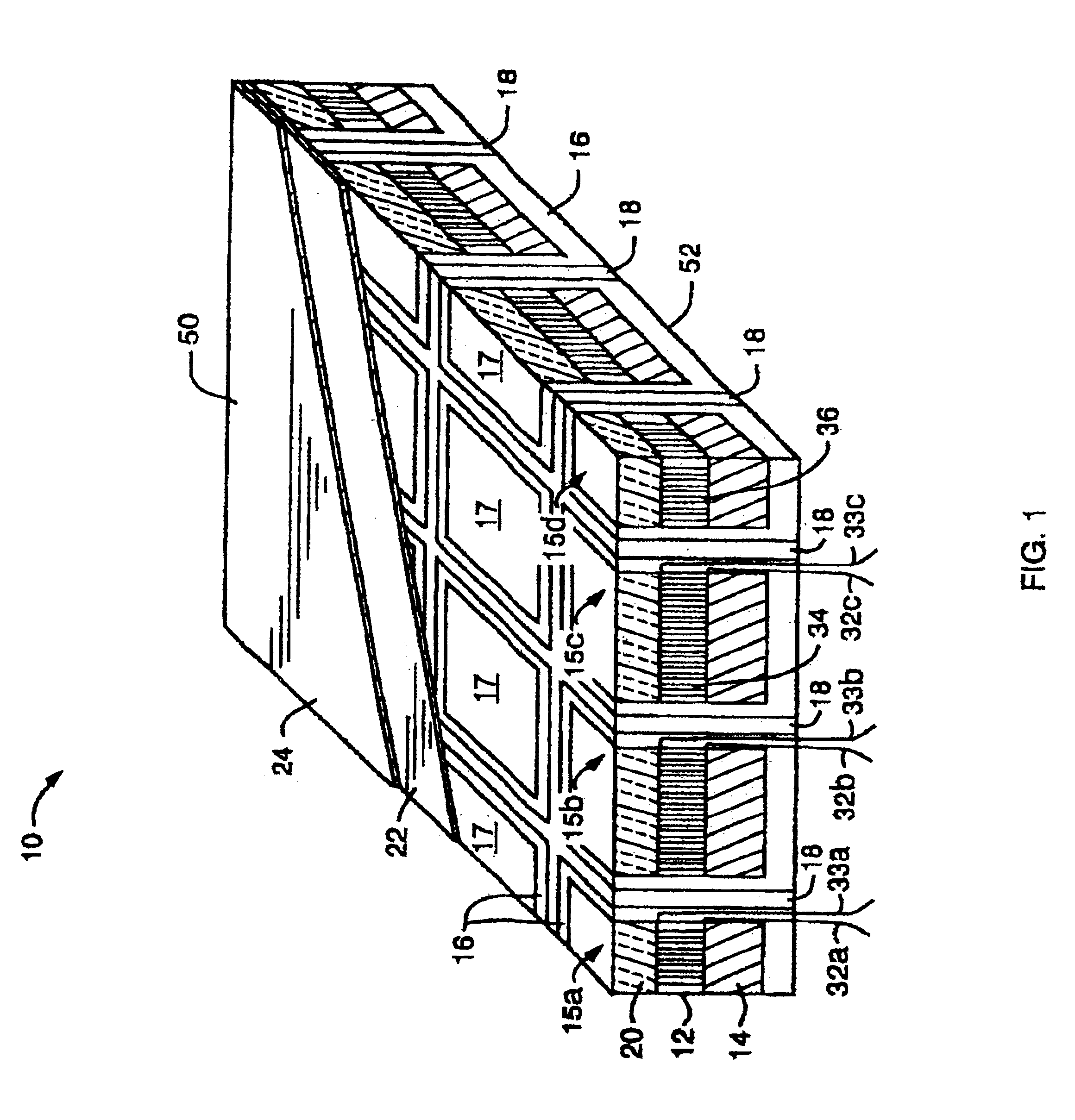
Referring to FIG. 1, a perspective view of an impact-reinforced, piezocomposite, acoustic transducer 10 is shown comprising an array of individual piezocomposite transducer elements 12, each placed in a single cell 17 of a honeycomb load supporting structure 18. In FIG. 1 the front 50 of the acoustic transducer 10 is shown as the upper side which is covered by a layer 24 of a fiber reinforced polymer, and the back 52 of the acoustic transducer 10 is considered the bottom side which is a soft matrix material 16.

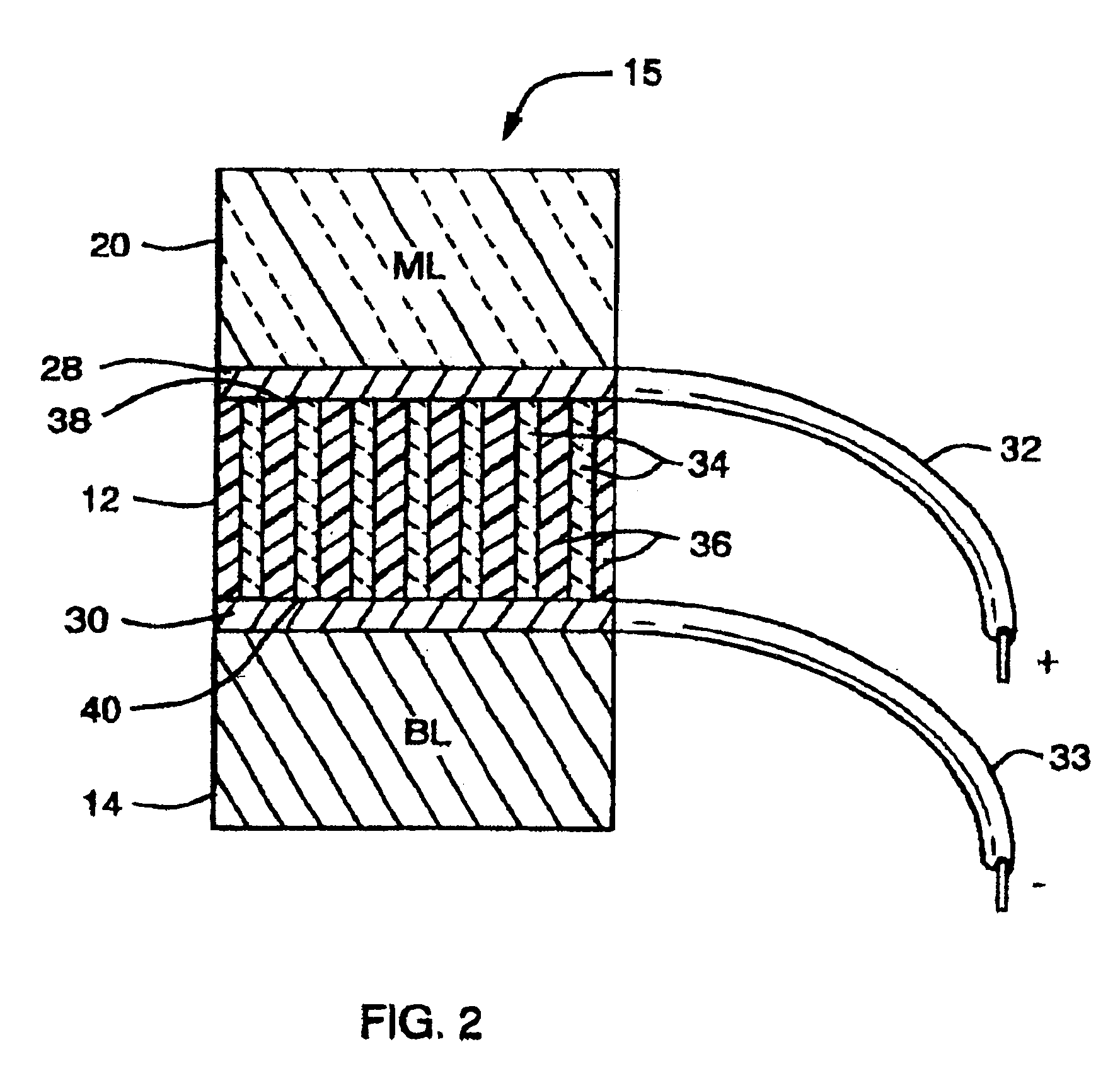
Referring now to FIG. 1 and FIG. 2, FIG. 2 shows a cross-sectional view of a stack 15 which occupies each cell 17. Each piezocomposite element 12 includes a plurality of piezoceramic rods 34 arranged parallel to one another in a regular array. The rods 34 of each element 12 are encapsulated in a polymeric matrix 36 to form a 1-3 connectivity configured composite body, then the encapsulated composite body is abraded or machined to expose both ends of each ceramic element at opp...


PUM


Abstract

An impact-reinforced piezocomposite transducer array comprises a load supporting structure having a plurality of cells, each of said cells comprises a piezocomposite transducer element. The load supporting structure comprises a honeycomb structure having a plurality of multi-sided cells or the structure comprises a plurality of cylindrical cells. The piezocomposite element includes a plurality of piezoceramic rods encapsulated in a polymeric matrix to form a 1-3 composite body. The transducer array may be used as a hydrophone or a transmitter in a rugged environment such as on the hull of an icebreaker ship.

Description

1. Field of the InventionThe present invention relates to piezoelectric ceramic-polymer composite transducer arrays, and particularly to acoustic transducer arrays which are suitable for rugged use.2. Description of Related ArtOne example of a rugged use for an acoustic transducer array is as a hydrophone for use as a sensor or transmitter on the hull of an icebreaker or surface-mounted on other equipment used in arctic waters.At present, such an array, e.g., that used as a hull-mounted array on a ship fitted as an icebreaker, is mounted beneath a reinforced plastic "array window" approximately four inches thick. The array is separated from the reinforced plastic window by a layer of seawater. Thus, the plastic window serves as a part of the ice-breaking shell of the ship, and the plastic window and the water layer act as a protective lens to shield the array from impact damage from contact with ice at and below the water surface.The plastic and water layers, however, also tend to d...

Claims


Application Information

Patent Timeline
Patent Type & Authority Patents(United States)
IPC IPC(8): B06B1/06G10K11/00H04R17/00H04R1/44
CPCB06B1/067H04R17/005G10K11/006H04R1/44
Inventor SCHMIDT, GERALD E.GLYNN, JAMES M.
Owner CHANNEL TECH GRP
Why Eureka
Try Eureka