Method of making a frame member into U-section and C-section panel profiles

a technology of u-section and c-section panel, which is applied in the direction of walls, roll mill control devices, manufacturing tools, etc., can solve the problems of high timber cost, low cost of steel framing in building construction, and localised deformation of studs

Inactive Publication Date: 2004-11-09
FRAMEMAX INC
View PDF21 Cites 26 Cited by
  • Summary
  • Abstract
  • Description
  • Claims
  • Application Information

AI Technical Summary

Problems solved by technology

The high costs of timber have made the use of steel framing in building construction cost effective.
Furthermore, because all components of a frame are made from members of the same cross-section, the required overlapping of members when a nog is inserted between the sides of a stud results in localised deformation of the stud.
Any deformations in the sides of the frame members results in an uneven planar surface of the frame with consequential difficulties in affixing a cladding to the frame with a preferred even finish.
A further limitation associated with conventional methods of constructing steel framing for building relates to the fact that the framing is manufactured off site in standard lengths.
The construction of a frame from such preformed lengths at a construction site is labour intensive and therefore costly.

Method used


Image

  • Method of making a frame member into U-section and C-section panel profiles
  • Method of making a frame member into U-section and C-section panel profiles
  • Method of making a frame member into U-section and C-section panel profiles

Examples


Embodiment Construction

This invention has several aspects all directed towards the efficient construction of metal frame assemblies. Hereafter, such assemblies and their components are referred to as steel frame members or assemblies since steel is the current metal of choice. However, it will be appreciated that other metals or alloys may be used.

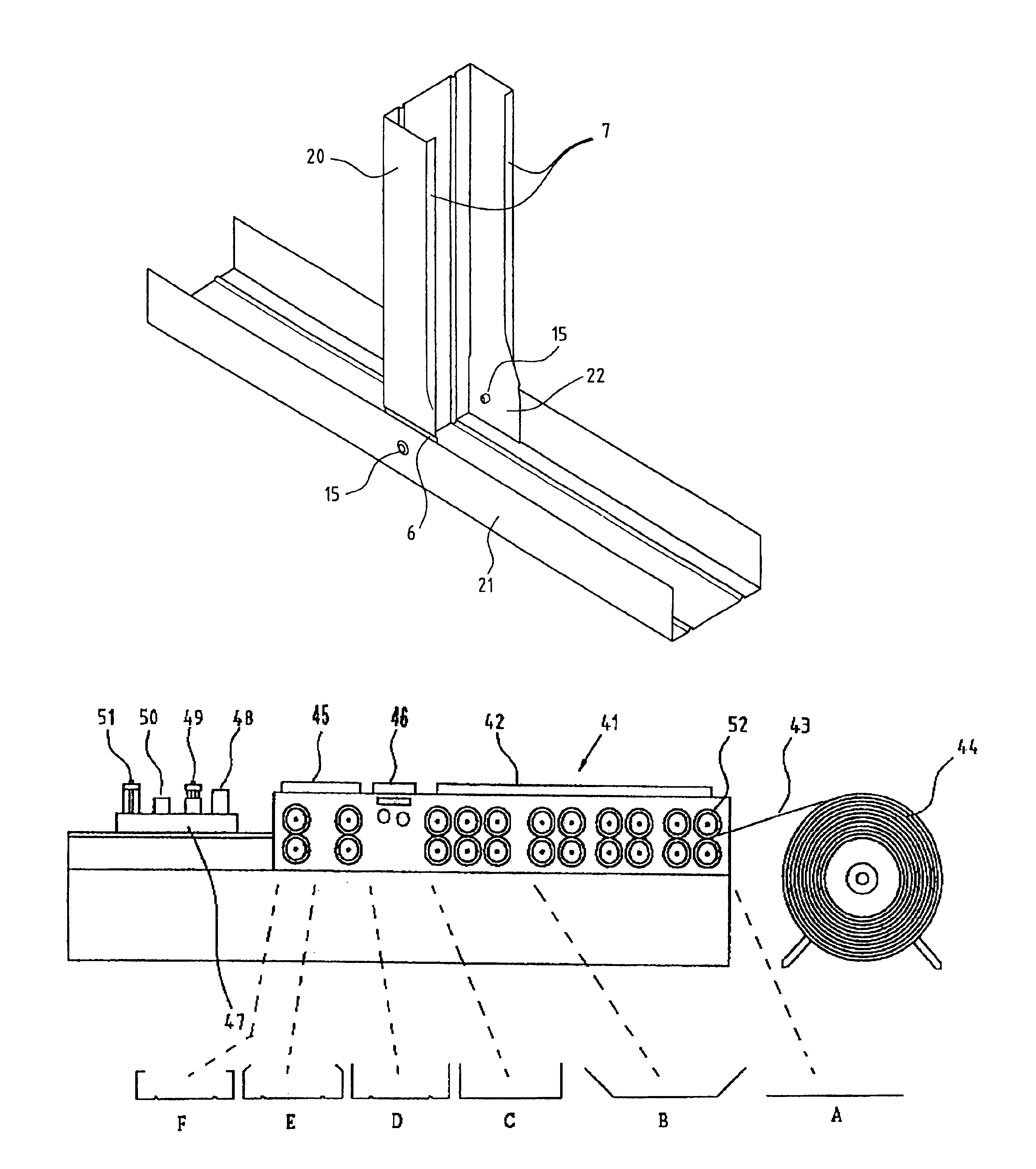
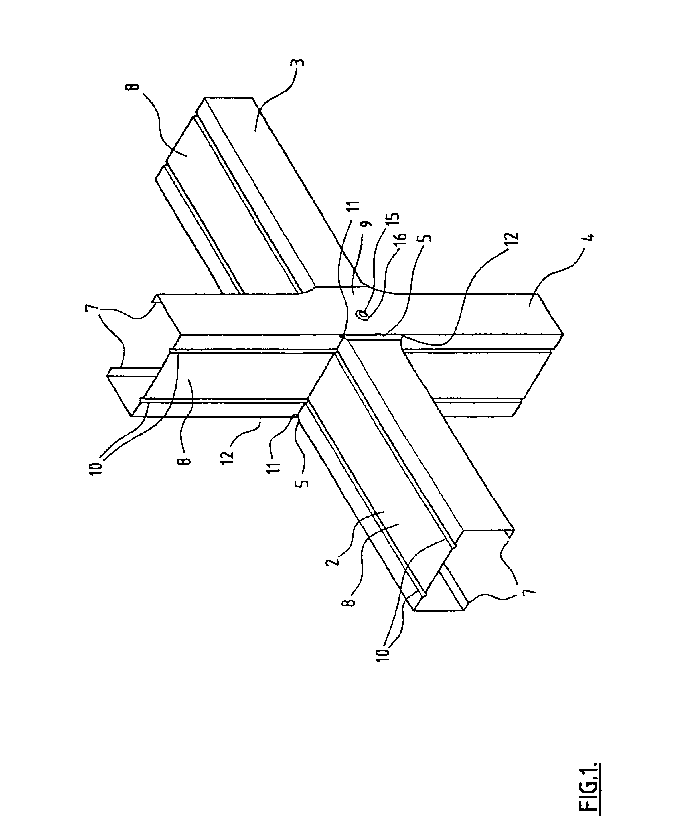
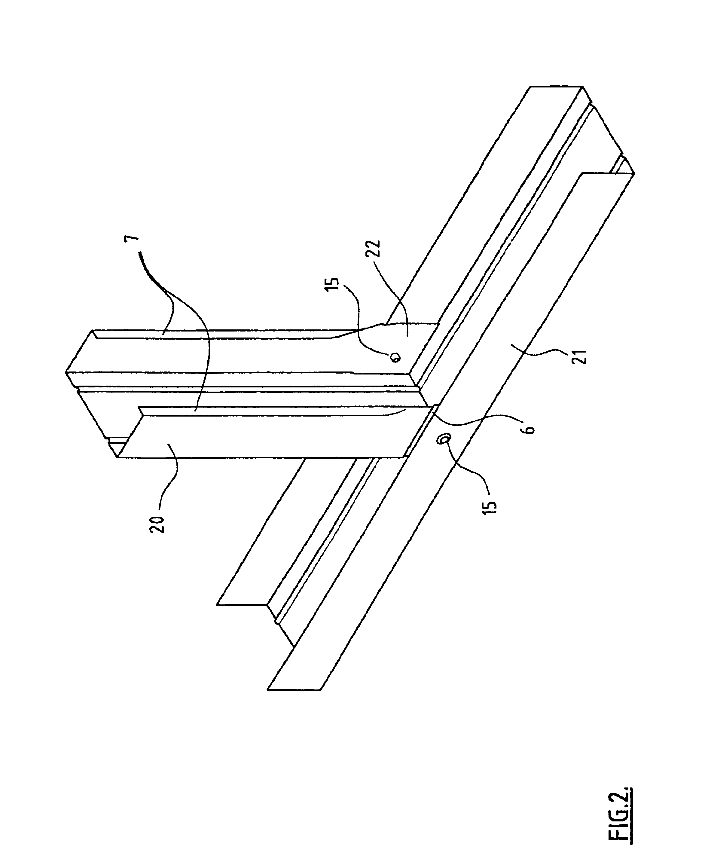
The first aspect of the invention relates to a method of construction of steel frame members in a form which facilitates assembly of the frame and which enables a frame to be produced with substantially planar surfaces. This is achieved by using roll forming apparatus to produce the steel frame channel members with a U-cross-section and forming this into a C-cross-section only at portions between or free from intended junctions. It is further facilitated by including one or more longitudinal ridges or slots in the base of the channel and increasing the depth of the or each ridge at regions which will need to be engaged within an interconnecting section. Increasi...


PUM

PropertyMeasurementUnit
depthaaaaaaaaaa
unit areaaaaaaaaaaa
areaaaaaaaaaaa

Abstract

This invention relates to metal framing (2, 3, 4), in particular steel framing for building construction. The invention also relates to a method of constructing a metal frame assembly (2, 3, 4) and roll forming apparatus (41) for producing metal framing for building construction. The individual components of the metal frame (2, 3, 4), and assembly made from these components is adapted to provide for a substantially even planar surface without deformations, to which a cladding may be attached with a preferred even finish. The invention also includes roll forming apparatus (41) adapted for producing metal framing (2, 3, 4) of this type, and particularly adapted to produce metal frame members (2, 3, 4) having a predominantly C-section profile (7), with one or more portions of a U-section profile (9, 6), the U-section (9, 6) and C-section (7) profiles formed simultaneously on the same sheet metal strip (43). The apparatus (41) is also adapted to form narrowing or swaging of the channel at same or all U-section portions (6). The overall method of constructing a building frame assembly of the invention includes recording data defining a unit area in which a frame assembly is to fit, processing the data to design a frame assembly to fit that unit area, and controlling operation of roll forming apparatus (41) by a computing means using the processed data, to produce frame members (2, 3, 4) cut and formed ready for assembly to produce the required design of frame assembly.

Description

This invention relates to metal framing, in particular steel framing, for building construction. The invention also relates to a method of constructing a metal frame assembly and apparatus for producing metal framing for building construction.BACKGROUND OF INVENTIONThe high costs of timber have made the use of steel framing in building construction cost effective. Known forms of steel frame construction require the riveting together of frame members which make up the studs and nogs of the frame. Since the frame members generally have a C-section it is necessary to bend back the lip at various points along a stud where a nog is to be interconnected. This bending out or flattening of the lip can introduce bending or deformation of the frame member. Furthermore, because all components of a frame are made from members of the same cross-section, the required overlapping of members when a nog is inserted between the sides of a stud results in localised deformation of the stud. Any deforma...

Claims


Application Information

Patent Timeline
Patent Type & Authority Patents(United States)
IPC IPC(8): B21D5/08B21D5/06B21D35/00E04B2/76
CPCB21D5/08E04B2/766E04B2/765B21D35/00
Inventor ELLIS, PHILIP GEORGE
Owner FRAMEMAX INC
Why Eureka
Try Eureka