
Friction clutch with separately controllable transmission brake

a transmission brake and friction clutch technology, applied in the field of friction clutches, can solve the problems of inability to adapt the force required for actuation of the friction clutch in an optimal manner to the actuation path, costing the device for wear compensation and maintenance, and disadvantageous construction of this type of structur

Inactive Publication Date: 2004-11-09
ZF SACHS AG
View PDF13 Cites 5 Cited by
  • Summary
  • Abstract
  • Description
  • Claims
  • Application Information

AI Technical Summary

Benefits of technology

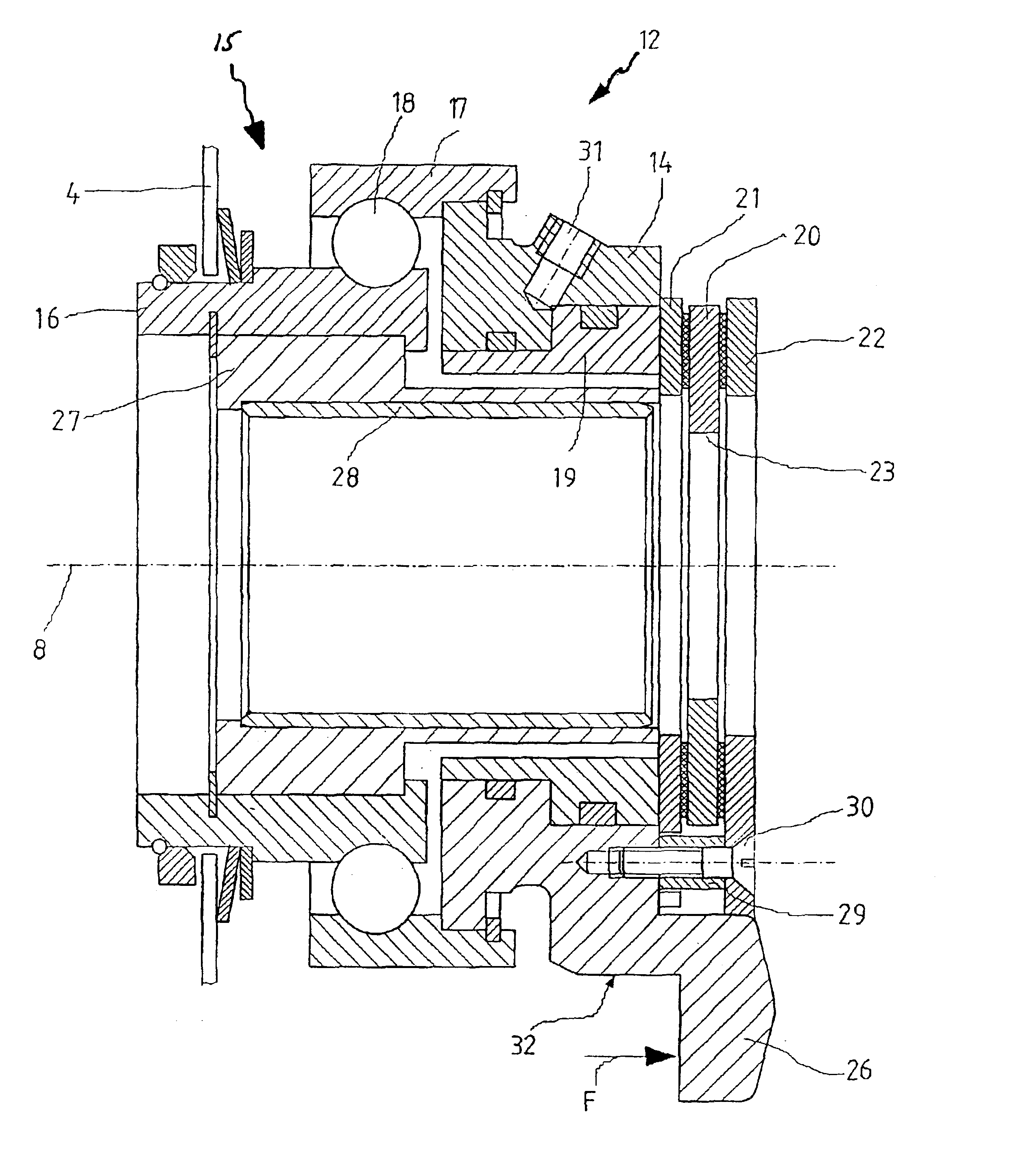
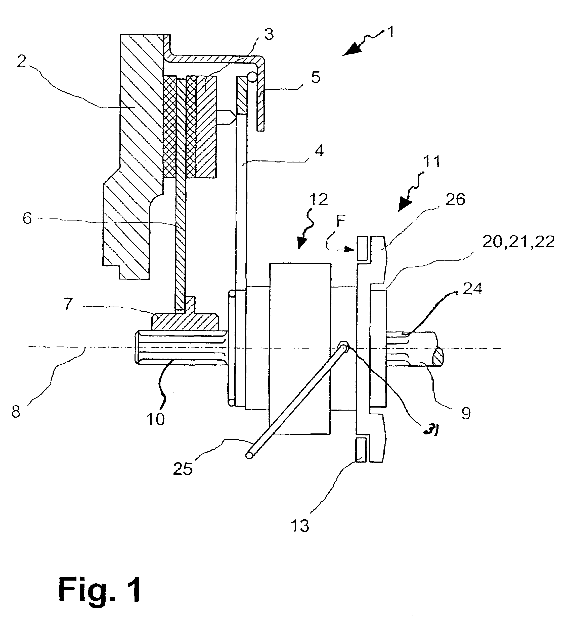
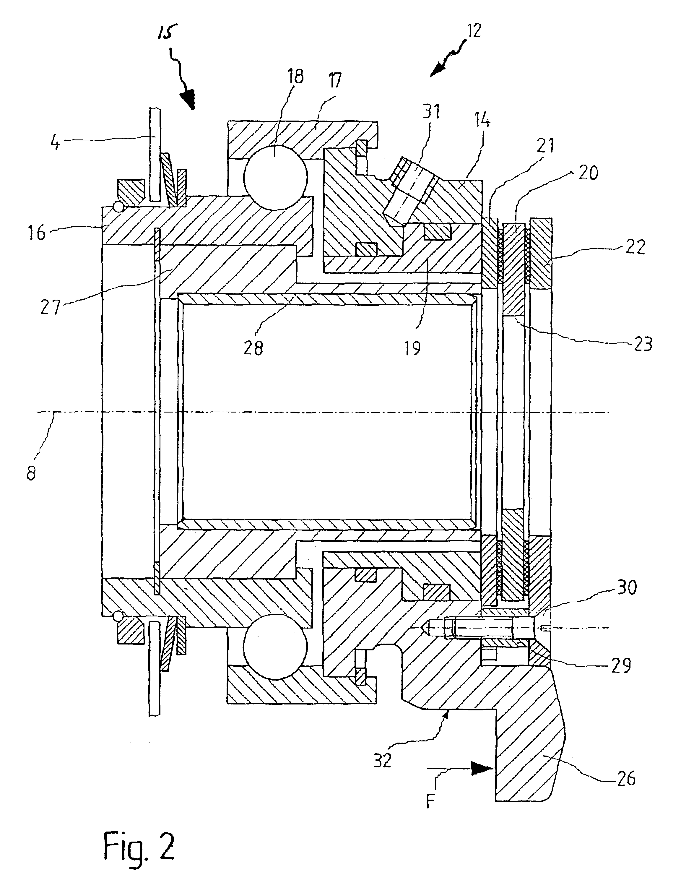
According to the present invention, this object is met by providing a friction clutch for a motor vehicle, that includes a clutch disk which can be coupled in frictional engagement with a crankshaft of an internal combustion engine. The clutch disk is connected to a transmission input shaft so as to be fixed with respect to rotation relative thereto and can revolve with the transmission input shaft around a common axis of rotation. The friction clutch includes an actuation system for engaging or disengaging the frictional engagement of the clutch disk which is arranged concentric to the transmission input shaft; and a transmission brake for reducing a rotational speed of the transmission input shaft during the shifting of the transmission. The transmission brake is actuated independently from the actuation system. By separating the clutch actuation and the actuation of the transmission brake, it is possible to orient the actuation system to the friction clutch in an optimal manner regardless of the actuation paths of the transmission brake.
According to another advantage of the present invention, all component parts of the transmission brake are integrated in the actuation system of the friction clutch and the friction clutch acts directly on the transmission input shaft. This construction substantially simplifies the handling of the entire actuation system, e.g., during assembly or during disassembly. Further, the direct action of the transmission brake on the transmission input shaft enables an arrangement that is independent from any existing transmission housing.
The actuation of the transmission brake is preferably carried out pneumatically. A pneumatic actuation of the transmission brake is advantageous insofar as there is a high degree of independence with respect to the transmission of the pneumatic medium; further, slight leakiness need not lead to any interference in the actuation system or in the friction clutch.
Preferably, the sliding sleeve is mounted on the transmission input shaft by the revolving bearing ring of the clutch release bearing so as to be axially displaceable. This results in an especially simple construction and is independent from the design of and from the axial distance of a transmission housing.

Problems solved by technology

A construction of this type is disadvantageous due to the fact that the actuation system of the friction clutch must be designed in such a way that it can execute a greater path than is required for the actuation of the friction clutch.
This means, for example, that the forces required for actuation of the friction clutch cannot be adapted in an optimal manner to the actuation path.
Further, a costly device for wear compensation and for maintaining the constancy of the actuation paths are provided in the prior art.

Method used


Image

  • Friction clutch with separately controllable transmission brake
  • Friction clutch with separately controllable transmission brake
  • Friction clutch with separately controllable transmission brake

Examples


Embodiment Construction

FIG. 1 shows the general construction of a friction clutch 1 with its actuation system 11. Only the upper half of the friction clutch 1 in longitudinal section is shown in FIG. 1. Flywheel 2 is fixedly arranged on a crankshaft of an internal combustion engine, not shown. The crankshaft and the flywheel 2 revolve about axis of rotation 8. Concentric about axis of rotation 8 is a transmission input shaft which extends facing away from the friction clutch 1 in the direction of the transmission, not shown. On its end facing the friction clutch 1, the transmission input shaft 9 has an external gearing 10 for receiving a hub 7 of a clutch disk 6 such that the hub 7 is fixed with respect to relative rotation. In its radial outer area, the clutch disk 6 has friction linings which are clamped between the flywheel 2 and a pressure plate 3 for transmitting a torque from the crankshaft to the transmission input shaft 9. A clutch housing 5, which extends at a distance from pressure plate 3 is af...


PUM


Abstract

A friction clutch, particularly for a motor vehicle, including a clutch disk which can be coupled in frictional engagement with the crankshaft of an internal combustion engine and which is connected by a hub to a transmission input shaft so as to be fixed with respect to rotation relative to it and can revolve with the latter around a common axis of rotation. The clutch further includes an actuation system for engaging or disengaging the frictional engagement of the clutch disk which is arranged concentric to the transmission input shaft, and a transmission brake for reducing the rotational speed of the transmission input shaft during determined shifting processes of the transmission. The transmission brake can be controlled independent from the actuation system of the friction clutch, and all component parts of the transmission brake are integrated in the actuation system of the friction clutch.

Description

1. Field of the InventionThe present invention is directed to a friction clutch, particularly for a motor vehicle, including a clutch disk which can be coupled in frictional engagement with the crankshaft of an internal combustion engine and which is connected by a hub to a transmission input shaft so as to be fixed with respect to rotation relative to it and can revolve with the latter around a common axis of rotation. The clutch includes an actuation system for producing or canceling the frictional engagement of the clutch disk which is arranged concentric to the transmission input shaft, and a transmission brake for reducing the rotational speed of the transmission input shaft during determined shifting processes of the transmission.2. Description of the Related ArtU.S. Pat. No. 4,579,203 discloses a friction clutch with a transmission brake in which the actuation system of the friction clutch can execute an additional path following the normal actuation path for the friction clu...

Claims


Application Information

Patent Timeline
Patent Type & Authority Patents(United States)
IPC IPC(8): F16D67/02F16D67/00F16D55/24F16D55/32
CPCF16D67/02F16D55/32
Inventor VOIT, HERBERT
Owner ZF SACHS AG
Learn More