Actuating device for a friction clutch device, possibly a dual or multiple friction clutch device

a technology of friction clutch and actuating device, which is applied in the direction of friction clutch, clutch, mechanical actuated clutch, etc., can solve the problems of oil leakage, excessive load on the takeoff shaft, and troublesome leakag

Inactive Publication Date: 2004-11-09
ZF SACHS AG
View PDF20 Cites 8 Cited by
  • Summary
  • Abstract
  • Description
  • Claims
  • Application Information

AI Technical Summary

Benefits of technology

The actuating device according to the invention can be produced compactly and at low cost. A high degree of functional (operational) reliability can also be achieved.
An especially preferred embodiment of the clutch device is characterized in that operating fluid can be supplied or, during operation, forcibly supplied at least to the areas where the support element and the (associated) actuating element engage with each other, by which mutual engagement the rotational movement is converted to the translational movement, the effect thus being to provide these engaging areas with wet lubrication. This wet lubrication makes it possible to reduce friction to an especially low level.

Problems solved by technology

The hydraulic dual CSC's used up to now are quite compact, but they suffer from the disadvantage that pressurized hydraulic oil must be supplied to the transmission housing shroud, which can lead to problems associated with the leakage of oil.
In particular, pulsating pressure loads on the seals lead to troublesome leaks, especially in the case of clutches of the so-called engaging type, that is, clutches of the NORMALLY OPEN type, upon which engaging forces must be exerted to engage the clutch.
Especially in the case of clutch arrangements of the NORMALLY OPEN type mentioned above, there is also the problem of how to absorb the axial forces which are produced in opposition to those exerted by the actuating arrangement and thus introduced into the clutch device.
The absorption of these opposing forces by way of the power takeoff shaft (possibly the crankshaft) of the drive unit is problematic, because this can subject the bearings of the power takeoff shaft to excessive load.
When conventional dual CSC's are used, however, it has been found that it is relatively difficult in terms of the design engineering involved to absorb the opposing forces in any other way.
The conventional approach is disadvantageous to the extent that the pins can be subjected to very heavy loads under certain conditions.
This can cause the natural wobbling frequency of the overall arrangement to increase, which is usually undesirable.
A further disadvantage of the conventional solution is that, when the actuating unit is to be installed in the drive train, it often proves difficult to thread the actuating unit onto the transmission-side pins.
Although it appears possible in principle to design the pins and the associated receiving holes in the actuating device with insertion bevels and / or with a comparatively large amount of clearance, this conceivable solution must usually be rejected in practice because it is necessary to ensure a certain minimum supporting length or load capacity, which would occupy too much space.
If this axial support occurs directly or indirectly via the power takeoff shaft of the drive unit, the bearings of the power takeoff shaft could be subjected to excessive load over the long term.

Method used


Image

  • Actuating device for a friction clutch device, possibly a dual or multiple friction clutch device
  • Actuating device for a friction clutch device, possibly a dual or multiple friction clutch device
  • Actuating device for a friction clutch device, possibly a dual or multiple friction clutch device

Examples


Embodiment Construction

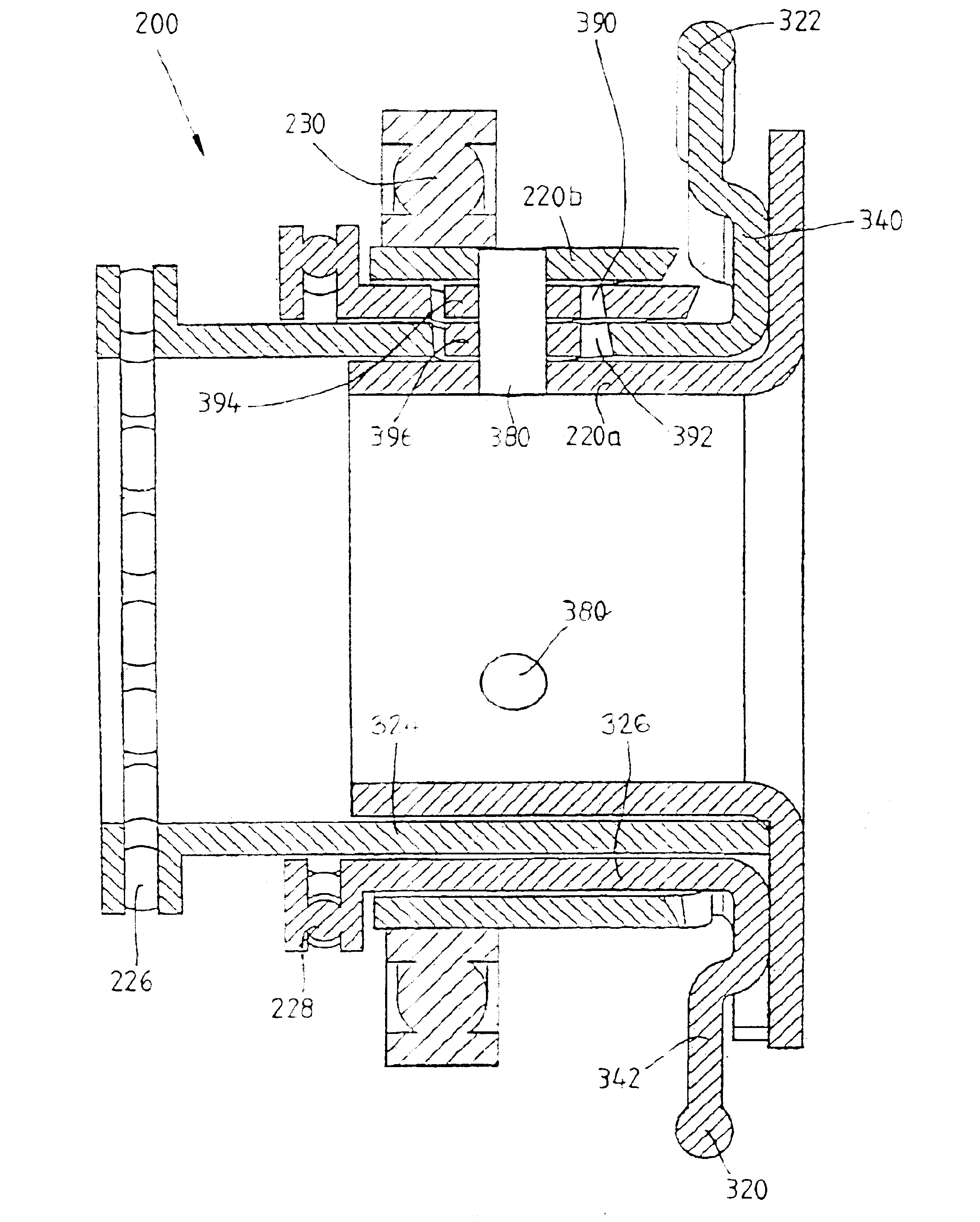
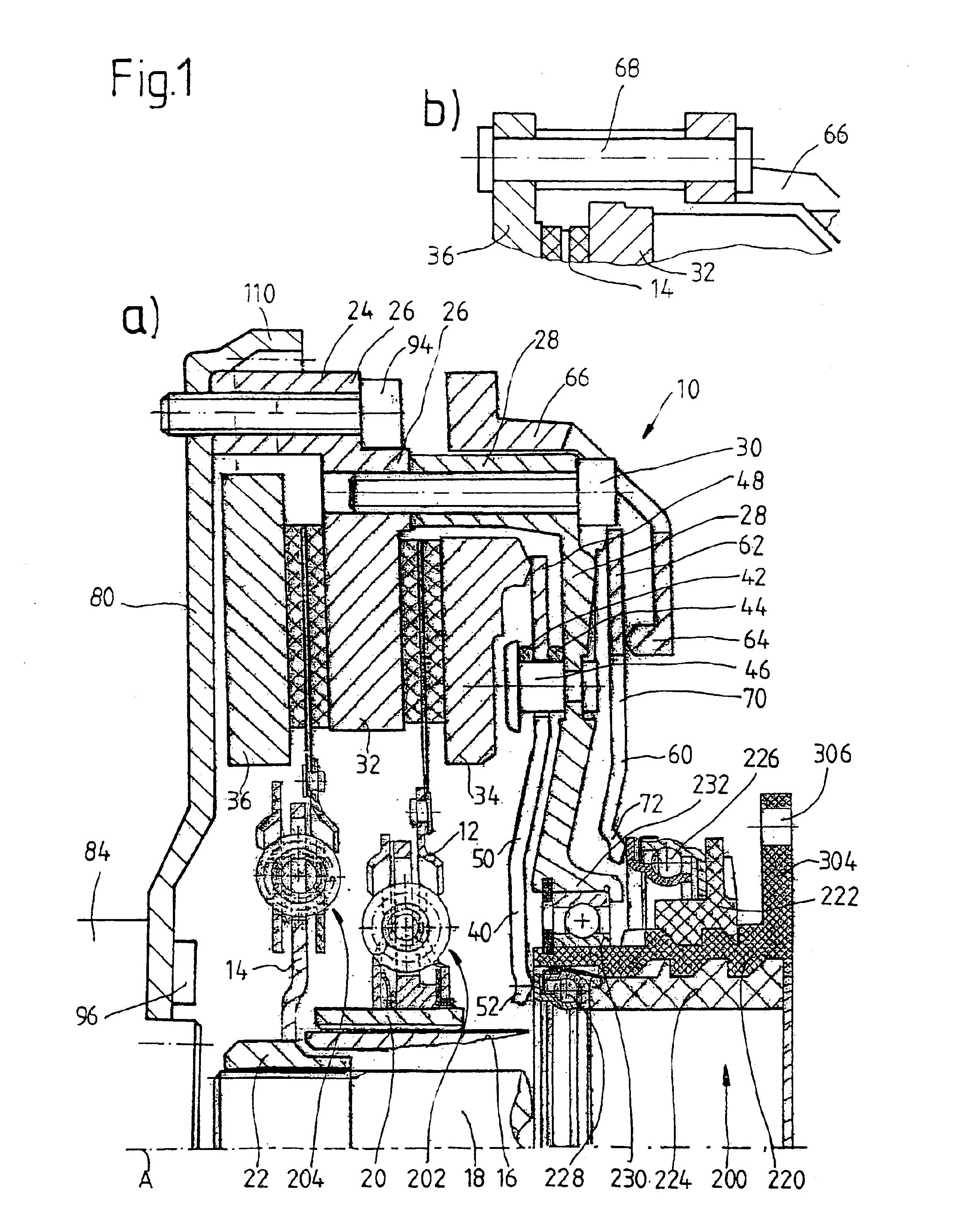
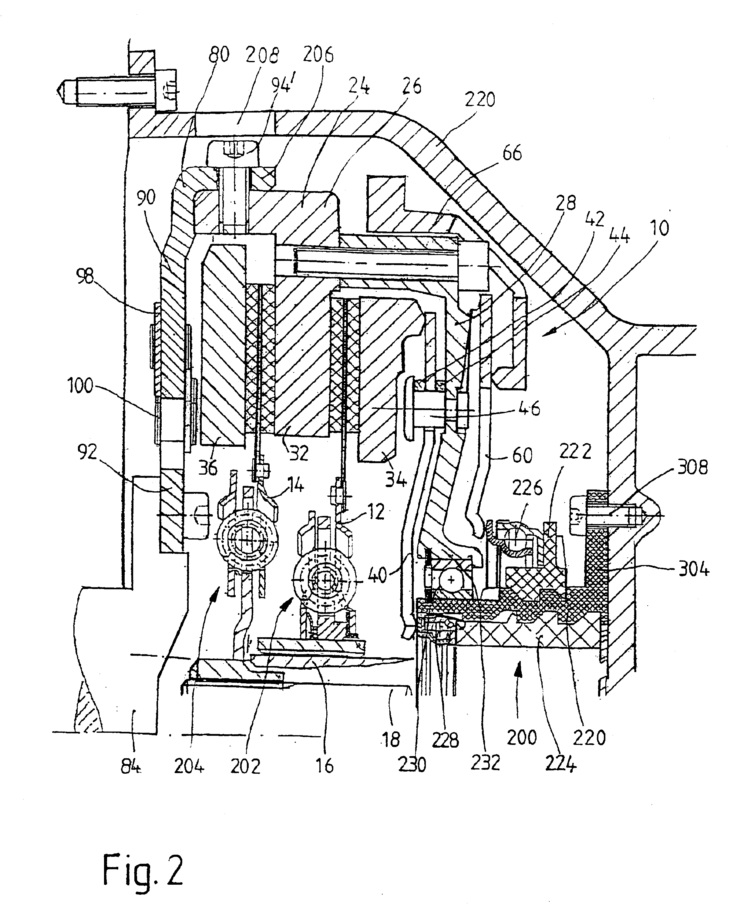
Various aspects of the invention are explained in greater detail below on the basis of special exemplary embodiments, namely, so-called dual clutches of the friction disk type, where, in the case of the exemplary embodiments of FIGS. 1 and 2, the dual clutches are of the NORMALLY CLOSED type, which are actuated by pushing, whereas the exemplary embodiments according to the invention shown in FIGS. 3 and 4 are dual clutches of the NORMALLY OPEN type, which are actuated by pushing. The aspects of the invention in question, however, are independent of the type of clutch and of the way in which it is actuated. The various inventive aspects can be implemented both in the case of simple clutches (with only one clutch arrangement) and in the case of dual clutches (or, in general, multi-clutch devices with two or more clutch arrangements), namely, both in the case of clutches of the NORMALLY OPEN type and those of the NORMALLY CLOSED type, and independently of the type of actuation, namely,...


PUM


Abstract

An actuating device for a friction clutch device installed in the drive train of a motor vehicle introduces actuating forces, especially clutch-engaging or clutch-releasing forces, to the friction clutch device to actuate at least one friction clutch of the friction clutch device in the engaging or releasing direction. At least one actuating element assigned to a friction clutch can be shifted axially relative to at least one support element, which is essentially fixed in the axial direction, to exert the actuating forces. The actuating element belongs to an actuator assigned to the clutch or can be shifted axially relative to the support element by the intermediate action of an actuator assigned to the clutch. The actuating element and the support element engage with each other in such a way that a rotational movement of the actuating element relative to the nonrotatably supported support element, this movement being imparted by the intermediate action of the actuator, is converted to an axial translational movement of the actuating element relative to the axially supported support element.

Description

1. Field of the InventionThe present invention pertains in particular (but not exclusively) to a so-called dual or multiple friction clutch device for installation in the drive train of a motor vehicle for the transfer of torque between a drive unit and a transmission, where the clutch device has a first friction clutch arrangement assigned to a first transmission input shaft and a second clutch arrangement assigned to a second transmission input shaft, and to a motor vehicle drive train equipped with this type of clutch device. With respect to the clutch device, the idea of the invention pertains primarily (but not exclusively) to so-called dual clutches of the friction disk type, for which it is known that an actuating device in the form of a hydraulic dual slave cylinder ("dual CSC") can be provided for the optional actuation of the first and / or of the second friction clutch arrangement to engage or release the clutch.2. Description of the Related ArtThe general goal is to provid...

Claims


Application Information

Patent Timeline
Patent Type & Authority Patents(United States)
IPC IPC(8): F16D23/14F16D23/00F16D23/12
CPCF16D23/14
Inventor HEIARTZ, MARKUSORLAMUNDER, ANDREASVOGT, SEBASTIANPAGELS, OLAFZINK, GEORGKLEUKER, CHRISTOPH
Owner ZF SACHS AG
Why Eureka
Try Eureka