Phase shifter having differently shaped interactive elements and an antenna system formed therefrom

a technology of interactive elements and phase shifters, which is applied in the direction of waveguides, household stoves or ranges, antennas, etc., can solve the problems of strip normal impedance disturbance, unreliable and susceptible to intermodulation products, and degradation of the antenna return-loss performance,

Inactive Publication Date: 2004-11-09
META PLATFORMS INC
View PDF7 Cites 17 Cited by
  • Summary
  • Abstract
  • Description
  • Claims
  • Application Information

AI Technical Summary

Benefits of technology

According to the invention there is provided a phase shifter element arranged to selectively vary the effective dielectric constant of a section of transmission line thereby changing the propagation velocity of the transmission line and varying the phase of signals of desired frequencies or frequency range passing through the transmission line the phase shifter element comprising a movable planar dielectric member of predetermined dielectric constant adjacent the transmission line, the planar dielectric member being provided with three or more discrete interactive dielectric segments extending from at least one edge thereof to moveably overlap the adjacent transmission line, where optimum dimensions of each interactive segment and optimum widths of gaps defined by opposite edges of adjacent segments are determined by computer optimisation means, such that the aggregate reflection of the signals passing through the transmission line is minimised.

Problems solved by technology

A disadvantage of this known method is that it is expensive, unreliable and susceptible to the generation of intermodulation products.
It is, however, well understood that the introduction of dielectric material under such a conductive strip causes the strip's normal impedance to be disturbed.
The resulting impedance mismatch would cause a degradation of return-loss performance of the antenna.
Such an arrangement imposes constructional disadvantages as well as limitations to the range of phase shift produced, which consequently imposes limits to the range of tilt.

Method used


Image

  • Phase shifter having differently shaped interactive elements and an antenna system formed therefrom
  • Phase shifter having differently shaped interactive elements and an antenna system formed therefrom
  • Phase shifter having differently shaped interactive elements and an antenna system formed therefrom

Examples


Embodiment Construction

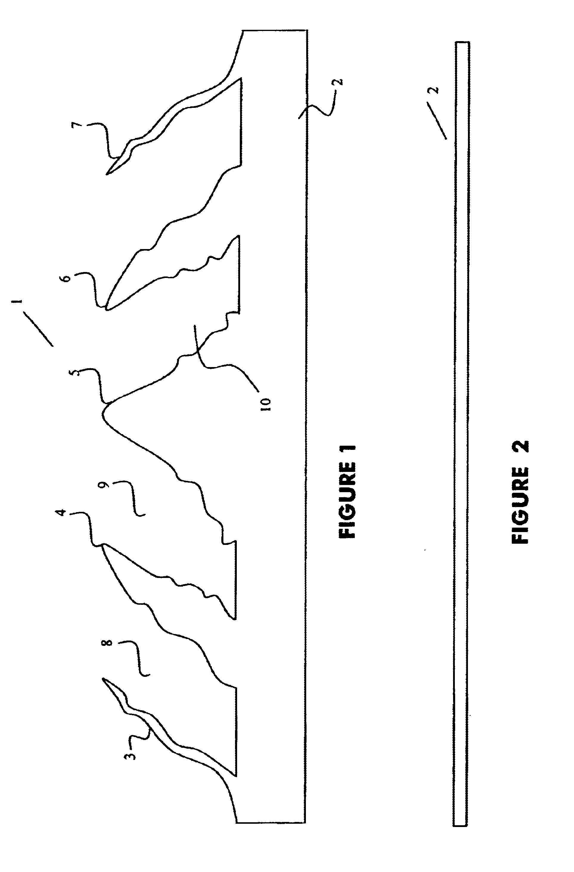
Referring to FIG. 1 of the drawings there is shown a planar dielectric element 1 comprising a rectangular body section 2 (see also FIG. 2) and five segments, 3, 4, 5, 6 and 7 extending from a major edge of body section 2. The segments are separated by four air gaps 8, 9, 10 and 11. The segments lie in the same plane as the body section. To improve structural rigidity of the dielectric element, the air gaps may be replaced by a dielectric material of a different dielectric constant to that of the material of the dielectric element 1. Alternately, the air gaps may be replaced by thinner portions of the same material as the dielectric element.

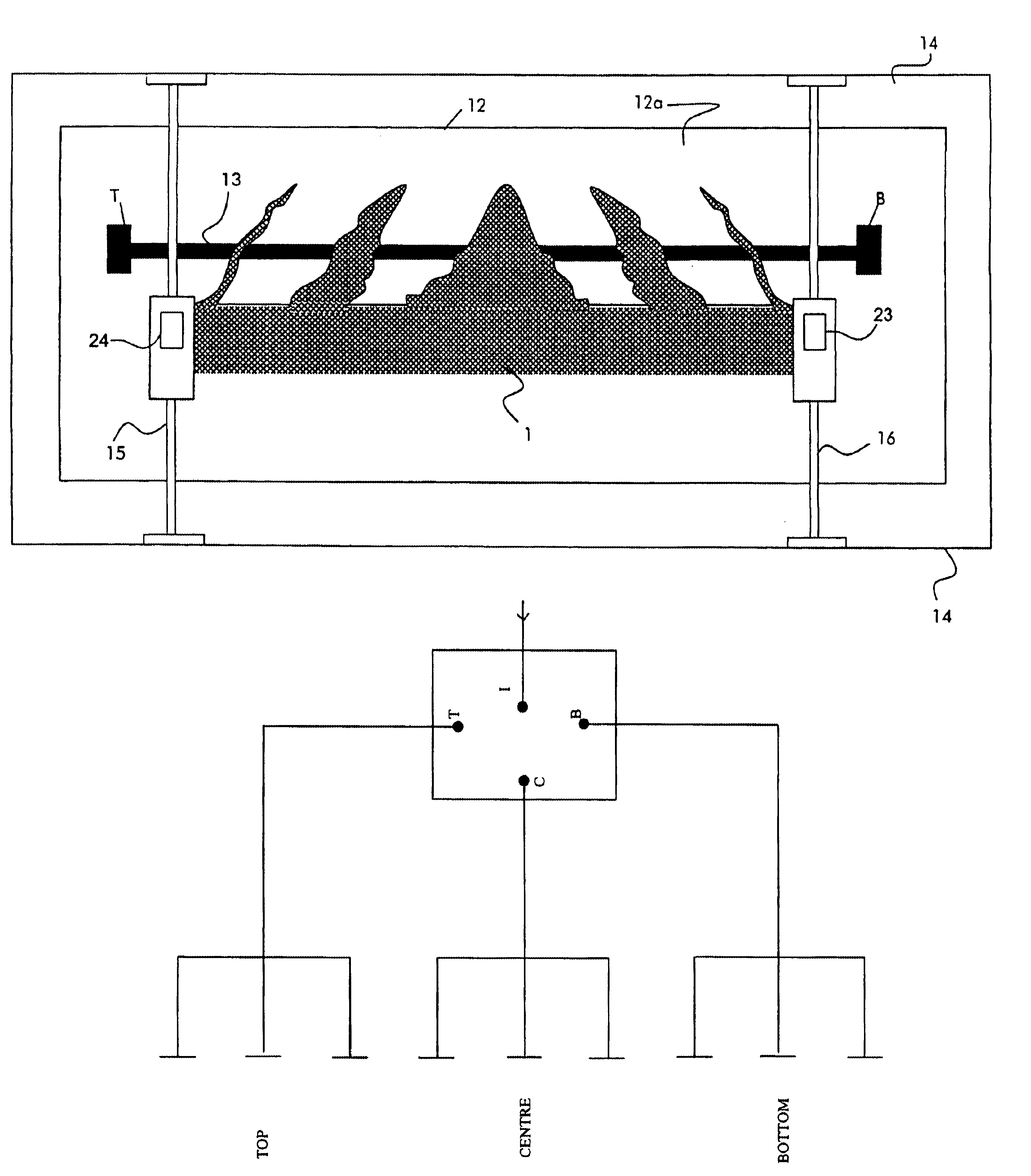
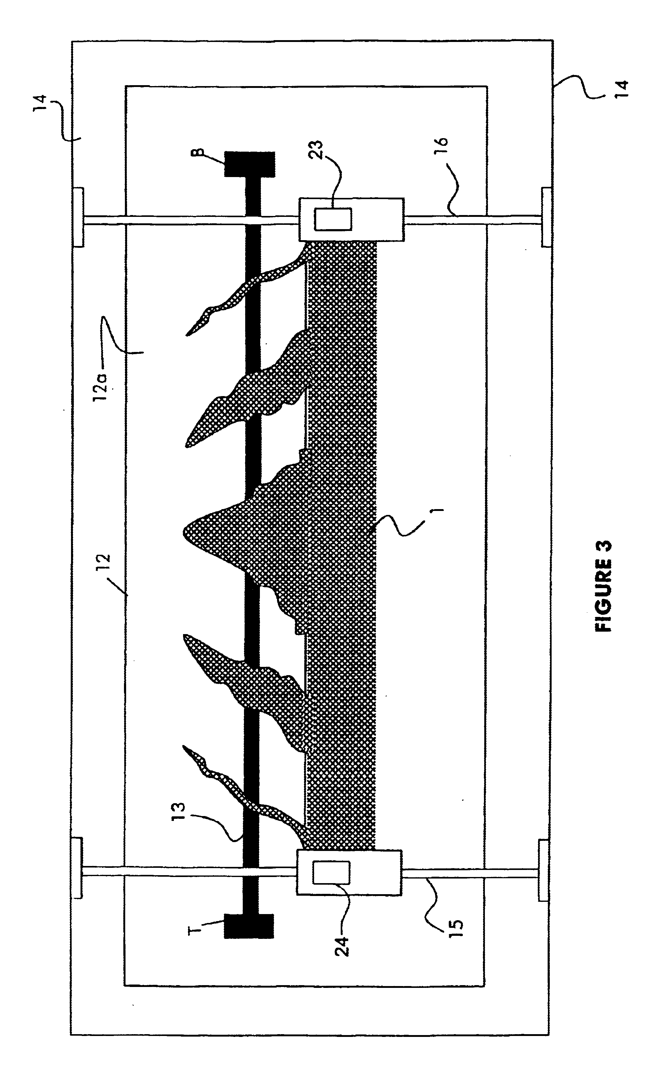
As shown in FIGS. 3 and 4, dielectric element 1 is slidably mounted and adjacent to the top surface of a PCB distribution element comprising a planar dielectric circuit board 12 supporting a conductive track 13 on a first surface 12a thereof. The conductive track and the dielectric circuit board form a transmission line whose distal ends terminate...


PUM


Abstract

A phase shifter element for selectively varying the phase of signals of desired frequencies or frequency range passing through an adjacent transmission line associated with, for example, an antenna array to electrically down-tilt the array's electromagnetic wave pattern. The phase shifter element comprises a planar dielectric member having at least three discrete coplanar interactive segments extending from an edge thereof and arranged to movably overlap the adjacent transmission line to vary its dielectric constant. Optimum dimensions of each interactive segments and optimum widths of gaps defined by opposite edges of adjacent segments being determined by a computer optimisation program, such that the phase shifter element achieves a wide operating frequency and minimum aggregate reflection.

Description

This invention relates to antennas and in particular to an arrangement to electrically down-tilt the electromagnetic wave pattern associated with a transmit antenna array, or electrically re-orient a receive antenna array.BACKGROUND OF INVENTIONIt is sometimes desirable to adjust the orientation of the electromagnetic wave pattern of a transmit antenna array, particularly a downward adjustment, typically 0 degrees to 15 degrees below horizontal, when the antenna is located at a higher altitude than other antennas that communicate with the transmit antenna array. The downward adjustment of the radiation pattern alters the coverage area and may enhance communication with mobile users situated in shadowed areas below the transmit antenna array.Besides actually mechanically tilting the entire antenna assembly, it is known to electrically down-tilt the radiation pattern by controllably varying the relative phase or phases between two or more radiating elements of the antenna array.One kn...

Claims


Application Information

Patent Timeline
Patent Type & Authority Patents(United States)
IPC IPC(8): H01Q3/30H01Q3/36H01P1/18
CPCH01Q3/36H01P1/184
Inventor MCDONALD, NOELWILLIAMS, CHARLIE G.
Owner META PLATFORMS INC
Why Eureka
Try Eureka