Pyramidal molded tooth structure

a pyramidal tooth and pyramidal technology, applied in the field of abrasive grit structures, can solve the problems of difficult manufacturing and maintenance of special equipment, high cost and inability to meet the objective of grinding wheels and the lik

Inactive Publication Date: 2004-11-23
L R OLIVER
View PDF8 Cites 51 Cited by
  • Summary
  • Abstract
  • Description
  • Claims
  • Application Information

AI Technical Summary

Benefits of technology

Another object of the present invention is to provide an improved tooth design to be molded of various hard grit materials.
Still another advantage of the present invention is the low cost to build and maintain the grinding wheel using pyramidal teeth according to the present invention.

Problems solved by technology

These structures along with other types of structures have the disadvantage in that the resulting tool may have grits of widely varying heights, erratic grit edges, flat spots or other irregular surfaces which tend to present an uneven grinding surface with relation to the work piece.
Many of these prior art grinding wheels and the like fail to meet this objective.
However, many of these prior art procedures are costly, time consuming and require special equipment that is hard to manufacture and maintain.
Furthermore, many of the prior art grinding wheel structures generally do not provide adequate space between the grinding particles.
This would result in diminished use for the life time of the tool due to particles of the work piece being lodged between the grit particles or extending over the grit particles such that contact between the individual grit particles and the work piece is reduced thereby inhibiting the grinding action and efficiency of the wheel.
However, many of these prior art grinding wheels have developed problems in that the diamonds are difficult to hold or bond to a surface in a manner that will not break off during the grinding process.
Therefore, generally the prior art grinding wheels using diamond grits initially worked well but after a period of use the diamond grit particles would eventually break away from the sub-straight structure thus reducing the effectiveness of the tool and reducing the tools long term grinding life.

Method used


Image

  • Pyramidal molded tooth structure
  • Pyramidal molded tooth structure
  • Pyramidal molded tooth structure

Examples


Embodiment Construction

)

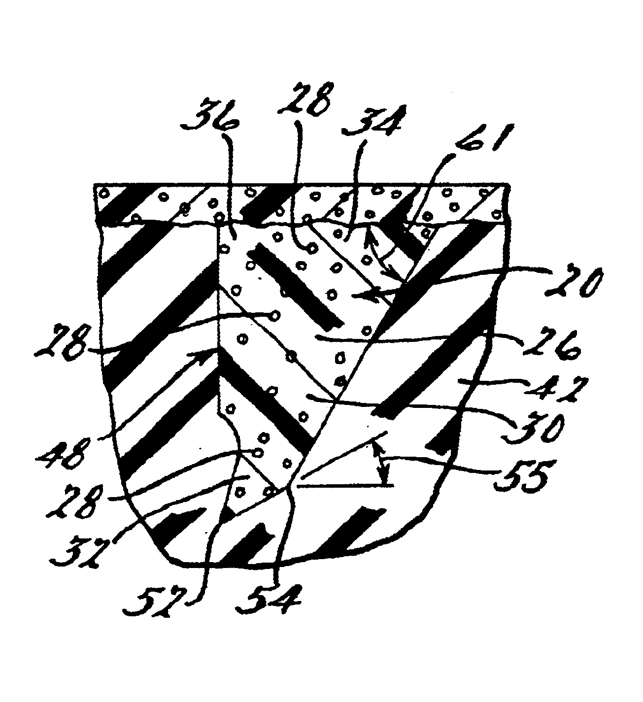
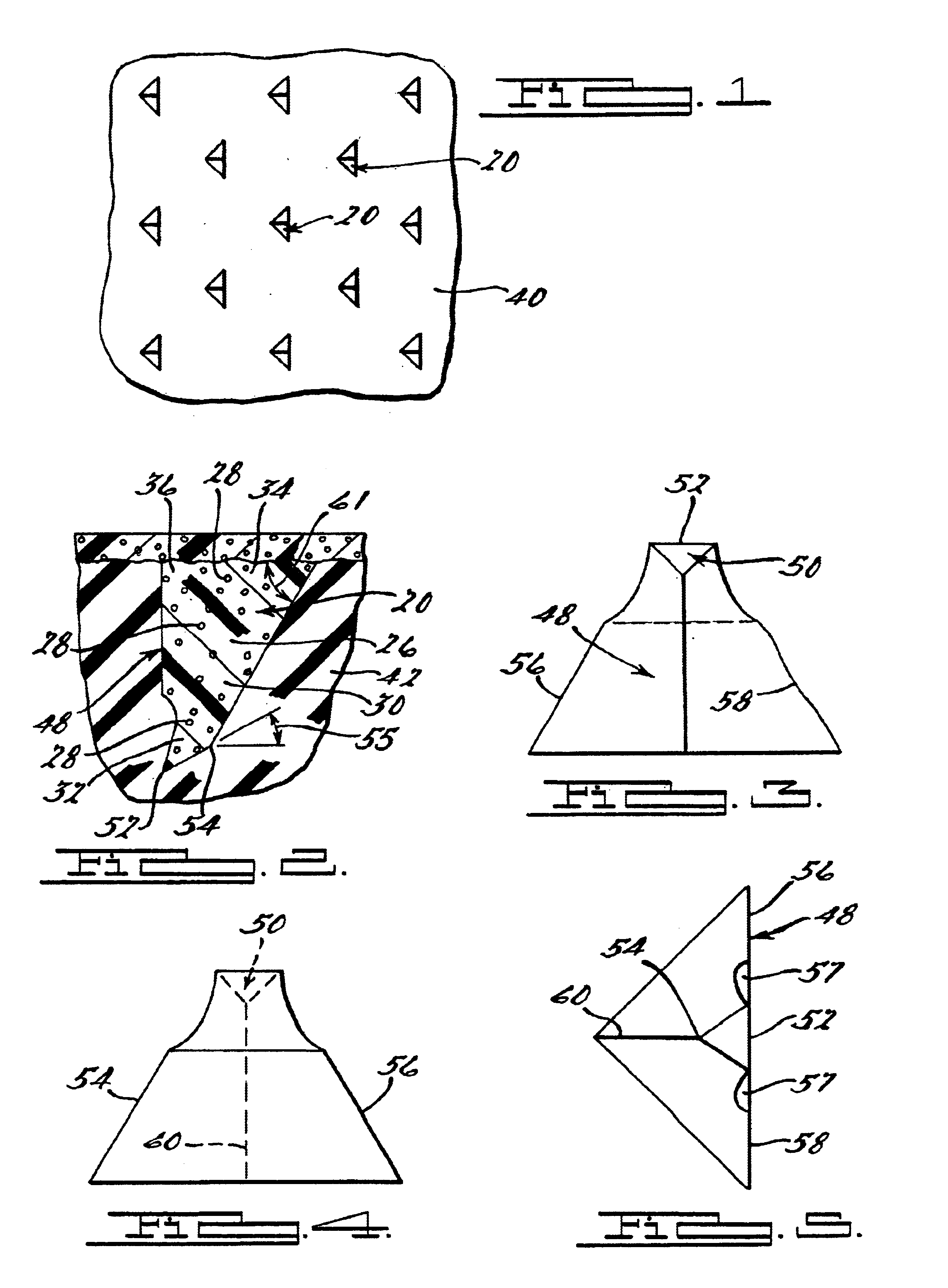
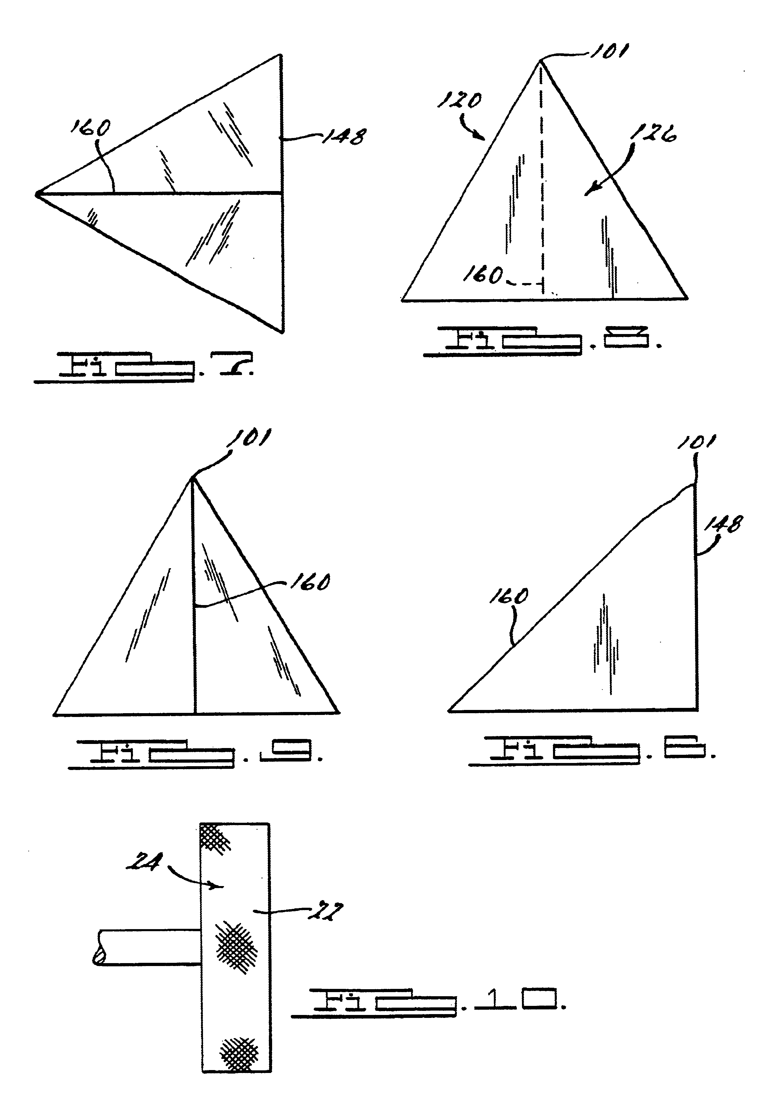
Referring to the drawings, the present invention of improved pyramidal molded teeth 20 for mating with a grinding wheel 22 are shown. It should be noted that the pyramidal molded teeth 20 will use an abrasive grit structure that is selectively attachable to a tool surface or a tool such as a grinding wheel 22 or the like. Applicant has developed various methods and apparatuses for connecting or molding teeth like structures to tool or surfaces and the present invention can be used with any of the applicant's previous inventions and therefore, the applicant hereby incorporates by reference prior U.S. Pat. Nos. Re. 35,812 and 4,916,869.

The pyramidal molded teeth structure 24 comprises a plurality of pyramidal shaped teeth 20. Each of the teeth 20 includes a body portion 26. The teeth 20 are substantially the same height such that the teeth 20 are coplanar. At least one abrasive grit 28 particle is provided within the body portion 26 of the teeth 20. In one embodiment it is preferable...


PUM

PropertyMeasurementUnit
clearance angleaaaaaaaaaa
included angleaaaaaaaaaa
rake angleaaaaaaaaaa

Abstract

A molded tooth design of generally pyramidal form made of various hard grit materials for use on a grinding wheel for grinding non-metal materials. The tooth structure generally includes a raked face having a neutral to positive rake angle that terminates to a sharp point. The tooth structure also includes on the raked face edge portions below the point extending from both sides thereof having a predetermined clearance angle to increase penetration and reduce friction of the tooth during the grinding process. The tooth structure may also include at a top end of the rake face a truncated clearance surface which will produce a wider cutting edge that is flat, for use in attacking the work surface of the work piece being ground. The rake face of the tooth generally may also be formed to have positive rake in the truncated surface.

Description

1. Field of the InventionThe present invention generally relates to abrasive grit structures used in the grinding and shaping of various materials, and in particular relates to a molded pyramidal tooth structure for use in the cutting and grinding of non metal materials and compositions.2. Description of Related ArtAbrasive grit tool structures have been known for numerous years. Generally, the abrasive grit tool structures include devices such as grinding wheels, hand tools and the like which generally have an outer grit particle surface which is used to remove portions of a work piece for shaping and finishing a work piece. In many prior art structures abrasive grits have been attached to tool surfaces by placing a single layer of grit particles on a tool form and then binding the grits to the tool by using a brazing metal or by an electro plating coating which grips the grit particles. These structures along with other types of structures have the disadvantage in that the resulti...

Claims


Application Information

Patent Timeline
Patent Type & Authority Patents(United States)
IPC IPC(8): B24D18/00B24D11/00
CPCB24D18/0009B24D11/001
Inventor OLIVER, LLOYD R.
Owner L R OLIVER
Why Eureka
Try Eureka