Pretilt angle measuring method and measuring instrument

a technology of pre-tilt angle and measuring method, which is applied in the direction of instruments, optical apparatus testing, optical radiation measurement, etc., can solve the problems of not being able to detect requiring expensive photoelastic modulation elements (pem) for these measurements, and being difficult to achieve the effect of detecting the pretilt angle of liquid crystal cells

Inactive Publication Date: 2004-11-23
MITSUBISHI ELECTRIC CORP +1
View PDF5 Cites 26 Cited by
  • Summary
  • Abstract
  • Description
  • Claims
  • Application Information

AI Technical Summary

Benefits of technology

In accordance with the present invention, it is not necessary to use a plurality of lights having different wavelengths. Therefore, the pretilt angle can be determined within a short time by using a simple measurement apparatus.
In a preferred embodiment of the present invention, Stokes parameters for a plurality of light incident angles are determined based upon the transmitted light intensity measured for a plurality of light incident angles, and then the pretilt angle of the sample having a twisted orientation is determined based upon the Stokes parameters. When the pretilt angle is determined by using the Stokes parameters, a simpler measurement apparatus can be used and the measurement time can be further shortened.
In another preferred embodiment of the present invention, an apparent retardation for a plurality of light incident angles is determined based upon the measured transmitted light intensity for a plurality of light incident angles, and then the pretilt angle of the element is determined based upon the apparent retardation When the pretilt angle is determined by using the apparent retardation, complex simulation becomes unnecessary. Therefore, the amount of calculations is greatly reduced.
The pretilt angle can be determined accurately by measuring the transmitted light intensity in such arrangement.

Problems solved by technology

Therefore, it is not suitable for detecting the pretilt angle of liquid-crystal cells having a twisted orientation direction, such as TN liquid-crystal cells and STN liquid-crystal cells.
Furthermore, an expensive photoelastic modulation element (PEM) is necessary for these measurements.
Therefore, the amount of calculations is enormous.
Furthermore, because the measurements must be performed with polychromatic light, the light source and the photodetector become complex.
Therefore, the same problems are encountered as those described with reference to the method disclosed in Japanese Laid-open Patent Application No. 9-152321.
Furthermore, the specification of Japanese Laid-open Patent Application No. 11-352449 does not disclose a specific method for calculating the pretilt angle.

Method used


Image

  • Pretilt angle measuring method and measuring instrument
  • Pretilt angle measuring method and measuring instrument
  • Pretilt angle measuring method and measuring instrument

Examples


first embodiment

An "extended Jones matrix method" or a "4.times.4 matrix method" can be used for the simulation. Accuracy can be increased by incorporating information about structural components, such as transparent electrodes or oriented films, into the simulation. The "4.times.4 matrix method" requires more computation that the "extended Jones matrix method." However, in accordance with the present invention, computation may be performed for a single wavelength. Therefore, the amount of computation may be reduced by comparison with multiple-wavelength computations using the "4.times.4 matrix method." For this reason, accuracy can be increased by changing the simulation method, even when samples are considered that have a large pretilt angle .theta..sub.s, thereby making it impossible to approximate the tilt angle .theta..sub.LC by a constant, or when the pretilt angles .theta..sub.s are different at the upper and lower boundaries.

In the present embodiment, a case will be considered in which the ...

second embodiment

The second embodiment of the present invention will be described below. In the second embodiment, the pretilt angle is determined by using Stokes parameters.

A method using Stokes parameters has been known as a method for representing the polarization state of light. The Stokes parameters of liquid-crystal cells can be calculated by using the transmitted light intensity measured in a state in which a quarter-wave plate or polarizer is disposed at the light incident side and light outgoing side of the liquid-crystal cell. This procedure is therefore very simple. A method for detecting the Stokes parameters is disclosed, for example, in Principles of Optics (M. Born, E. Wolf. Translated into Japanese by Kusagawa and Yokoda. Published by Tokai Daigaku Shuppankai) or Japanese Patent No. 3023443.

A method for detecting Stokes parameters will be described below.

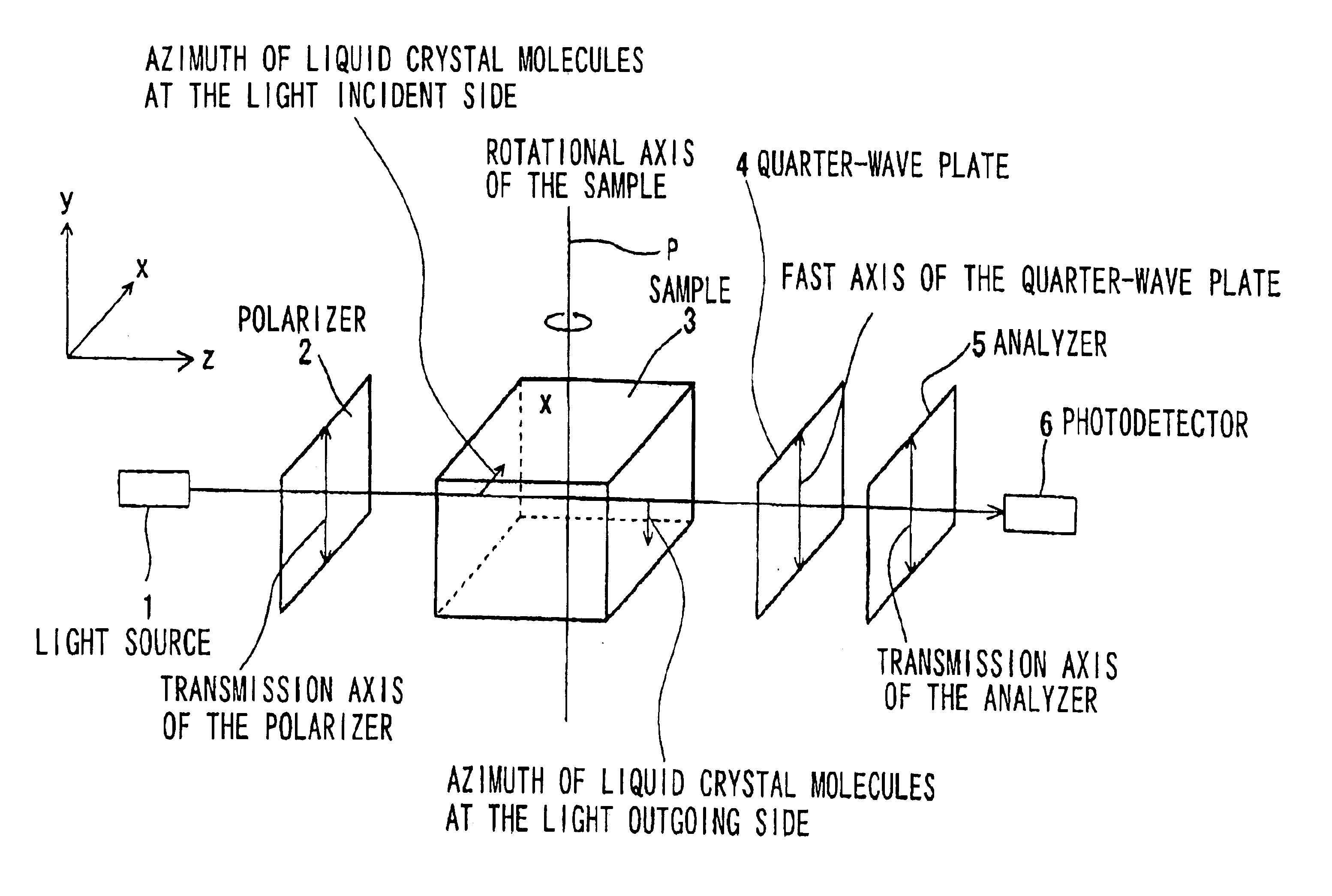
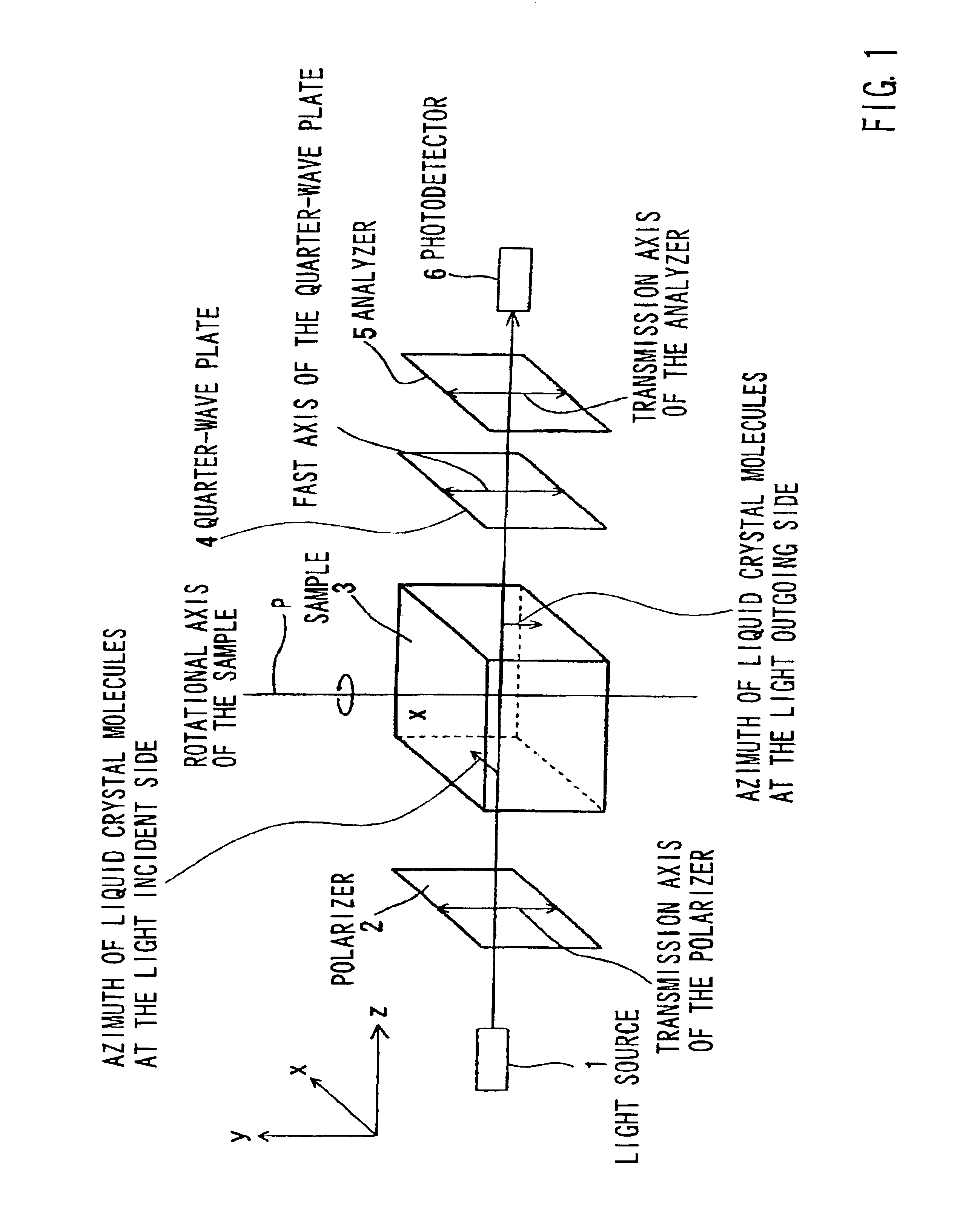
For example, a measurement apparatus shown in FIG. 1 can be used for measuring the transmitted light intensity necessary in order t...

third embodiment

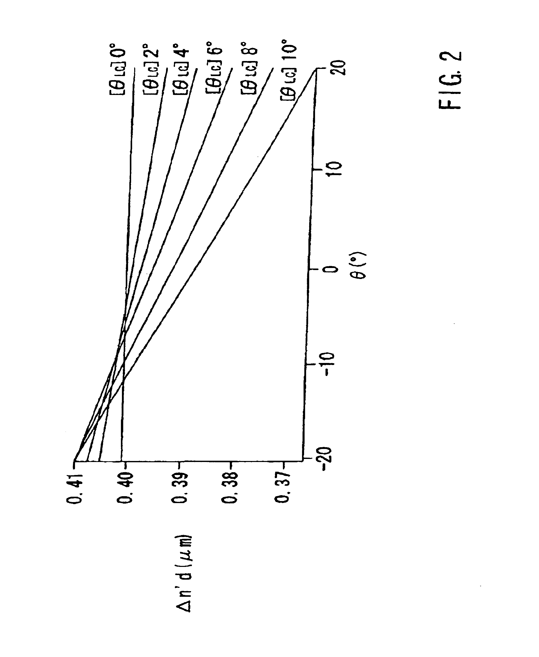
The apparent retardation .DELTA.n'(.theta.)d can be determined not only by a method using Stokes parameters. Thus, various methods can be used for this purpose, provided that the methods can detect the dependence of the apparent retardation .DELTA.n'(.theta.)d on the light incident angle .theta..

A third method for detecting the transmitted light intensity based upon the dependence of the apparent retardation .DELTA.n'(.theta.)d on the light incident angle .theta. will be described below. This embodiment is especially effective when the pretilt angle is determined for a sample having a twisted orientation in which the twist angle is about .+-.90.degree., as in a liquid-crystal cell.

The transmissivity T(.theta.) of the sample having a twisted orientation, which is disposed between a polarizer and an analyzer, can be represented by [Equation 19]: ##EQU14##

.gamma. is the angle between the transmission axis (polarization axis) of the polarizer and the transmission axis (polarization axis...


PUM

PropertyMeasurementUnit
angleaaaaaaaaaa
angleaaaaaaaaaa
pretilt angle θsaaaaaaaaaa

Abstract

An apparatus for detecting a pretilt angle is comprised of a light source 1, a polarizer 2, a liquid-crystal cell 3, a quarter-wave plate 4, an analyzer 5, a photodetector 6, and a processing device. The processing device receives from the photodetector transmitted light intensities of light that is transmitted through the liquid-crystal cell 3 at a plurality of light incident angles. The processing device calculates Stokes parameters corresponding to the plurality of light incident angles based upon the transmitted light intensity corresponding to the plurality of light incident angles. Furthermore, an apparent retardation corresponding to the plurality of light incident angles is determined based upon the Stokes parameters corresponding to the plurality of light incident angles. The pretilt angle of the liquid-crystal cell 3 is determined based upon the determined apparent retardation corresponding to the plurality of light incident angles.

Description

The present invention relates to methods and apparatus for detecting a pretilt angle of an element in which the direction of orientation of molecules is twisted between a light incident side and a light outgoing side.BACKGROUND TECHNOLOGYLiquid-crystal display devices using liquid-crystal cells have been widely used in monitors and displays due to their characteristics, such as low weight, small thickness, and low energy consumption. The display principle of liquid-crystal cells is based upon the fact that the direction of orientation of liquid crystal molecules changes and the polarization state of the incident light on the liquid-crystal cell is modulated when a voltage is applied across the liquid-crystal cell.Various types of liquid-crystal cells utilized in liquid-crystal displays are known. Twisted nematic liquid-crystal cells (herein referred to as "TN liquid-crystal cells") and super twisted nematic liquid-crystal cells (herein referred to as "STN liquid-crystal cells") have...

Claims


Application Information

Patent Timeline
Patent Type & Authority Patents(United States)
IPC IPC(8): G01B11/26G01N21/21G01M11/00G02F1/13G02F1/1337
CPCG02F1/1309G01B11/26
Inventor KURATA, TETSUYUKINISHIOKA, TAKAHIROTOGASHI, YOSHIHIROSATO, SUSUMU
Owner MITSUBISHI ELECTRIC CORP
Why Eureka
Try Eureka