Heat exchanger
a heat exchanger and heat exchanger technology, applied in the field of gasflow heat exchangers, can solve the problems of high pressure drop and require substantial fan power
- Summary
- Abstract
- Description
- Claims
- Application Information
AI Technical Summary
Benefits of technology
Problems solved by technology
Method used
Image

Examples
first embodiment
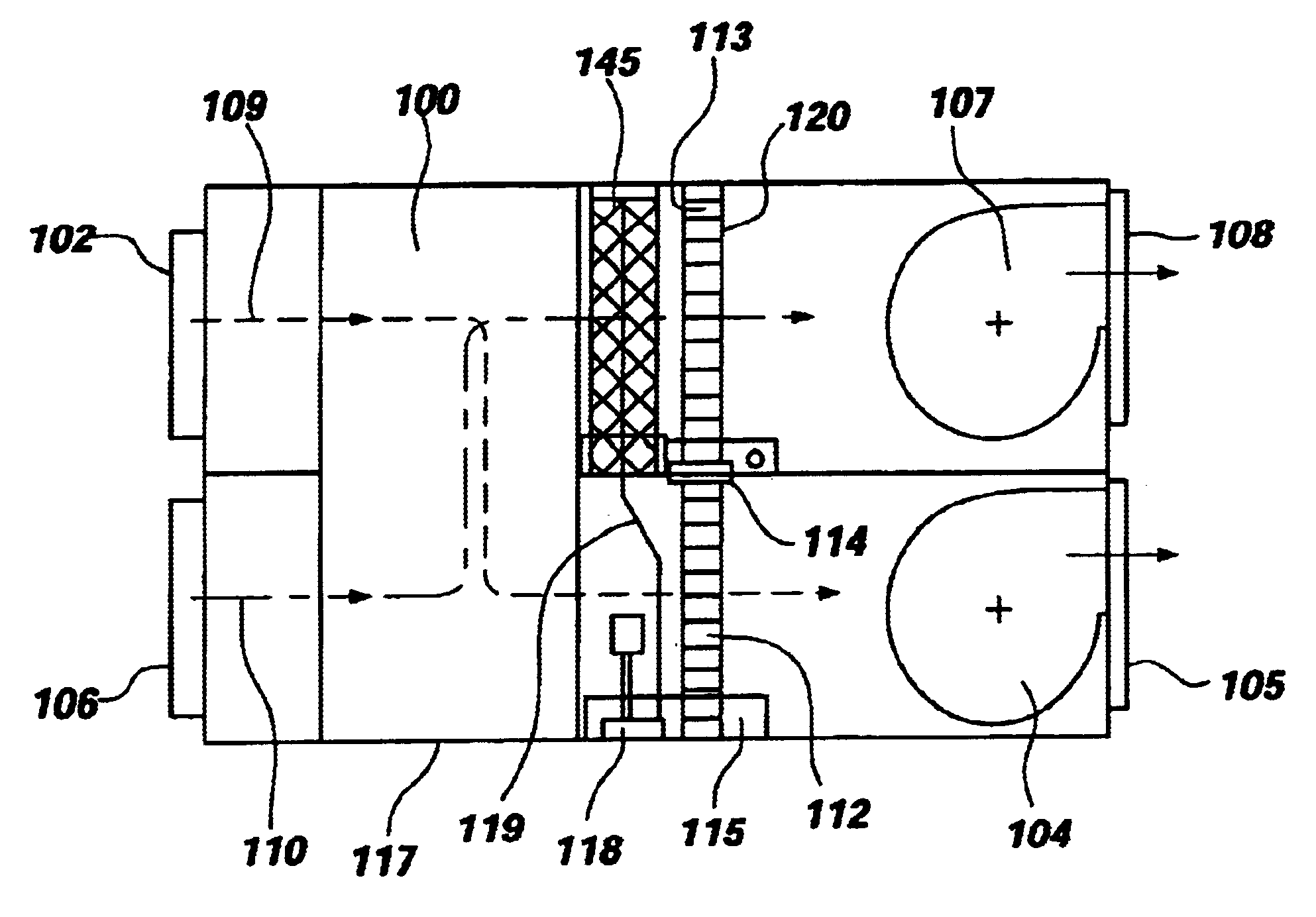
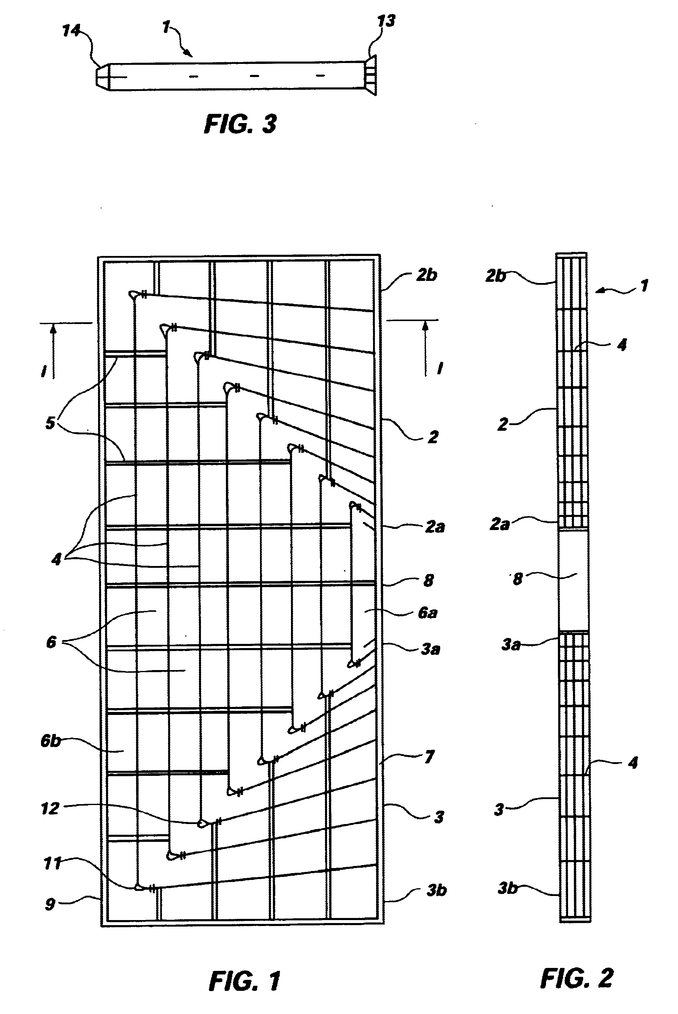
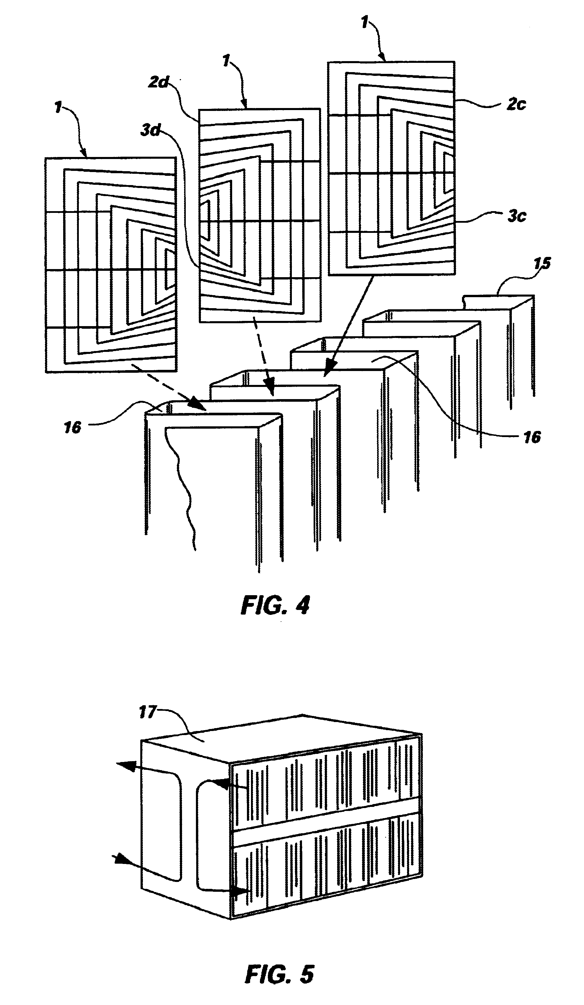
In a first embodiment, the present invention as shown in FIGS. 1-5 is a gas-flow heat exchanger stack, contained within a closed casing 17. In a manner similar to that disclosed in U.S. Pat. No. 5,829,513 the gas-flow heat exchanger comprises a set of parallel, spaced, heat conductive areas providing between them a stack of pockets 16 each containing baffles 4 which define a platen of passageways 6 guiding the gas-flow path through the pocket between the inlet and outlet openings 2, 3.
Each pocket contains a removable frame 1 as shown in FIG. 1, which has inlet openings 2 and outlet openings 3 at each end of the gas-flow path. Frame 1 has a multiple set of thin guiding strips (baffles) 4 which together define a plurality of nested substantially U-shaped passageways 6 extending between inlet openings 2 on the upper side of the frame, and the outlet openings 3 on the lower side of frame 1. Webs 5 are of thin rectangular cross section and extend edgewise across frame 1 to act as turbule...
second embodiment
An advantage of a heat exchanger in accordance with the second embodiment shown in FIGS. 6-9, is that a number of such heat exchangers may be assembled in series (side by side) to form a larger heat exchanger assembly, by aligning the line of outlets 23 of one heat exchanger with the line of inlets 22 of an adjacent heat exchanger and so on. This allows for even greater heat exchange efficiency between the primary and secondary gas flow circuits.
FIG. 10 show the construction of inlet openings 22 in which two flat parallel and spaced side strips 31 form continuations of the sides of the frame 1, so that the openings 22 are formed between them. The end portions of the baffle strips 30 are integrally molded with the side strips 31. Each of the side strips 31 is provided with a rib 32 extending along its length and which fits into a flute 33, see FIGS. 11 and 12 formed in the opposed side face of the neighboring frame 21. The foil 35 is trapped at its edges between the ribs 32 and the f...
third embodiment
FIG. 14 shows a perspective and exploded schematic view of part of the gas heat exchanger of the The plastic frame 41 is inserted into each of the pockets 56 where every alternate frame 41 is turned through 180 degrees to allow the flow of gas to both sides of the stack.
The sinuously wound foil 55 is in a similar configuration and material to that of foil 15 of the first embodiment.
The heat exchanger described in abovementioned embodiments is suitable for use in a number of air-conditioning or ventilation systems that exchange sensible and latent heat of outdoor air. The heat exchanger can be used in an air-conditioning system supplying outdoor air into the return air of an existing heating and or cooling plant, or just installed separately to service outdoor air into a room. The Total Heat Air Exchanger can be incorporated into a Fan Coil Unit for supplying 10% to 100% of outdoor air with the transfer of energy from the exhaust air. The latent transfer may be around three times mo...
PUM
| Property | Measurement | Unit |
|---|---|---|
| humidity | aaaaa | aaaaa |
| temperature | aaaaa | aaaaa |
| temperature | aaaaa | aaaaa |
Abstract
Description
Claims
Application Information
 - R&D
- Intellectual Property
- Life Sciences
- Materials
- Tech Scout
- Unparalleled Data Quality
- Higher Quality Content
- 60% Fewer Hallucinations
Browse by: Latest US Patents, China's latest patents, Technical Efficacy Thesaurus, Application Domain, Technology Topic, Popular Technical Reports.
© 2025 PatSnap. All rights reserved.Legal|Privacy policy|Modern Slavery Act Transparency Statement|Sitemap|About US| Contact US: help@patsnap.com