
Clutch device connected centrally on the input side to a rotating shaft or rotating component in a motor vehicle drive train

a technology of a clutch device and a central input side, which is applied in the direction of interengaging clutches, couplings, road transportation, etc., can solve the problems of not being able to connect the clutch device, using the flexplate either directly or indirectly, to the power takeoff shaft (possibly the crankshaft, the drive unit)

Inactive Publication Date: 2004-12-14
ZF SACHS AG
View PDF8 Cites 28 Cited by
  • Summary
  • Abstract
  • Description
  • Claims
  • Application Information

AI Technical Summary

Benefits of technology

"The invention is about a motor vehicle drive train with a multi-clutch device, especially a dual clutch device, installed between a drive unit and a transmission. The clutch device is connected to a power takeoff shaft through a torque-transmitting arrangement, which can be a flexible plate or a separate component. The technical effect of the invention is that it allows for a simpler and more efficient assembly process of the clutch device and the torque-transmitting arrangement, as they can be installed as a single unit without the need for separate components. Additionally, the invention provides a more compact and cost-effective solution for motor vehicle drive trains."

Problems solved by technology

If the clutch disks are already premounted in the clutch device, it is usually no longer possible in cases where the clutch device is already mounted on the drive unit to gain access to the screw holes located on the reference circle, which means that it is impossible to mount a preassembled unit comprising the flexplate and the clutch device itself, as a single structural unit, on the drive unit, that is, it is impossible to connect the clutch device, using the flexplate, either directly or indirectly, to the power takeoff shaft (possibly the crankshaft) of the drive unit.
This assembly procedure is very complicated and also highly susceptible to error, because it is difficult to verify that the assembly work has been carried out properly, especially that the flexplate has been properly connected to the clutch device.
In the case of motor vehicle clutches, axial impact and vibrational excitations as well as wobbling excitations emanating from the drive unit can cause problems.
The flexplates usually used to connect the clutch device to the power takeoff shaft of the drive unit, especially to the crankshaft of an internal combustion engine, are unable to absorb or to equalize such wobbling movements sufficiently, nor are they able to absorb or to equalize axial vibrations sufficiently.
Even if all the components are within the prescribed manufacturing tolerances, it is therefore possible for an undesirable force-fit in the axial direction to occur when the overall module is installed in its the proper position in the drive train.

Method used


Image

  • Clutch device connected centrally on the input side to a rotating shaft or rotating component in a motor vehicle drive train
  • Clutch device connected centrally on the input side to a rotating shaft or rotating component in a motor vehicle drive train
  • Clutch device connected centrally on the input side to a rotating shaft or rotating component in a motor vehicle drive train

Examples


Embodiment Construction

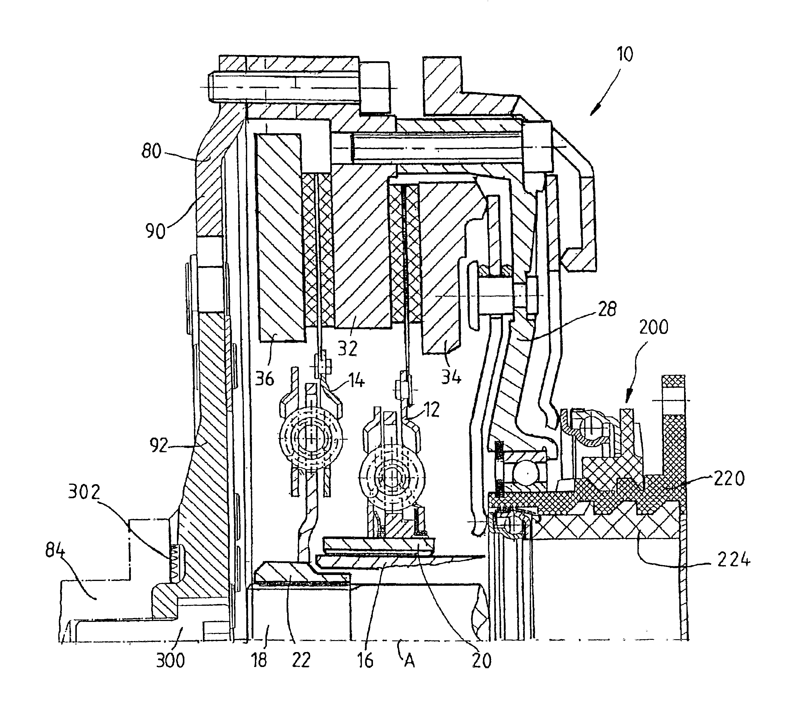
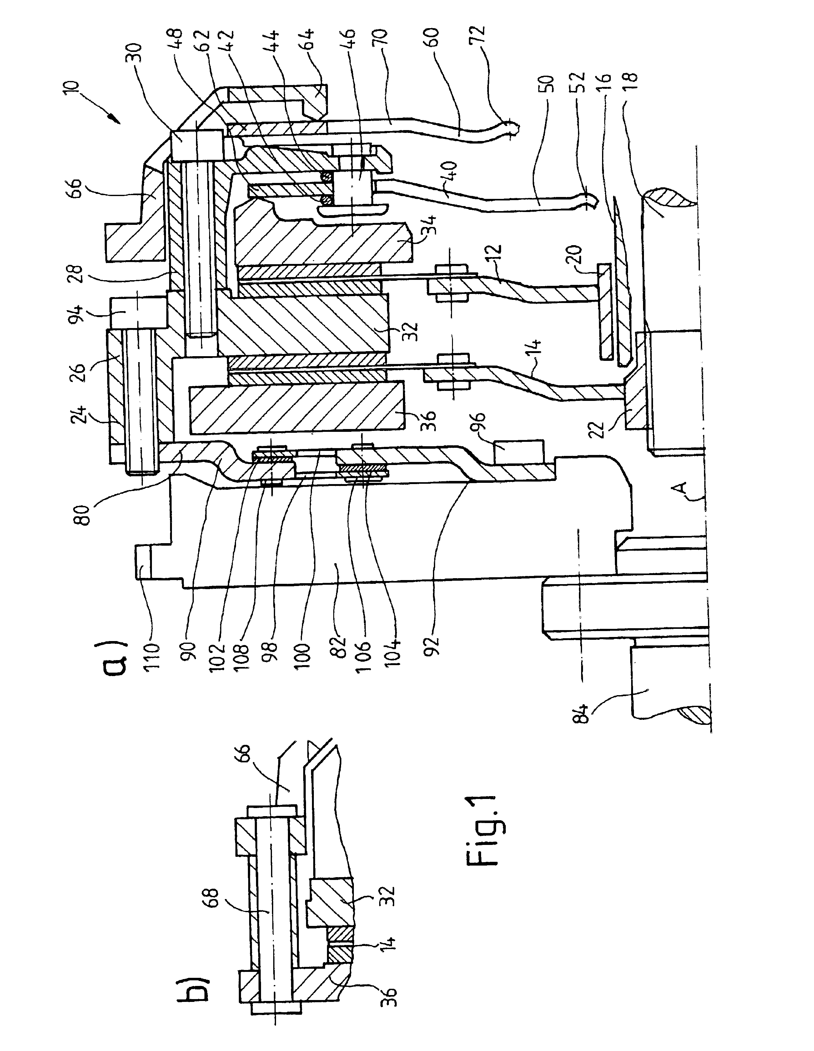
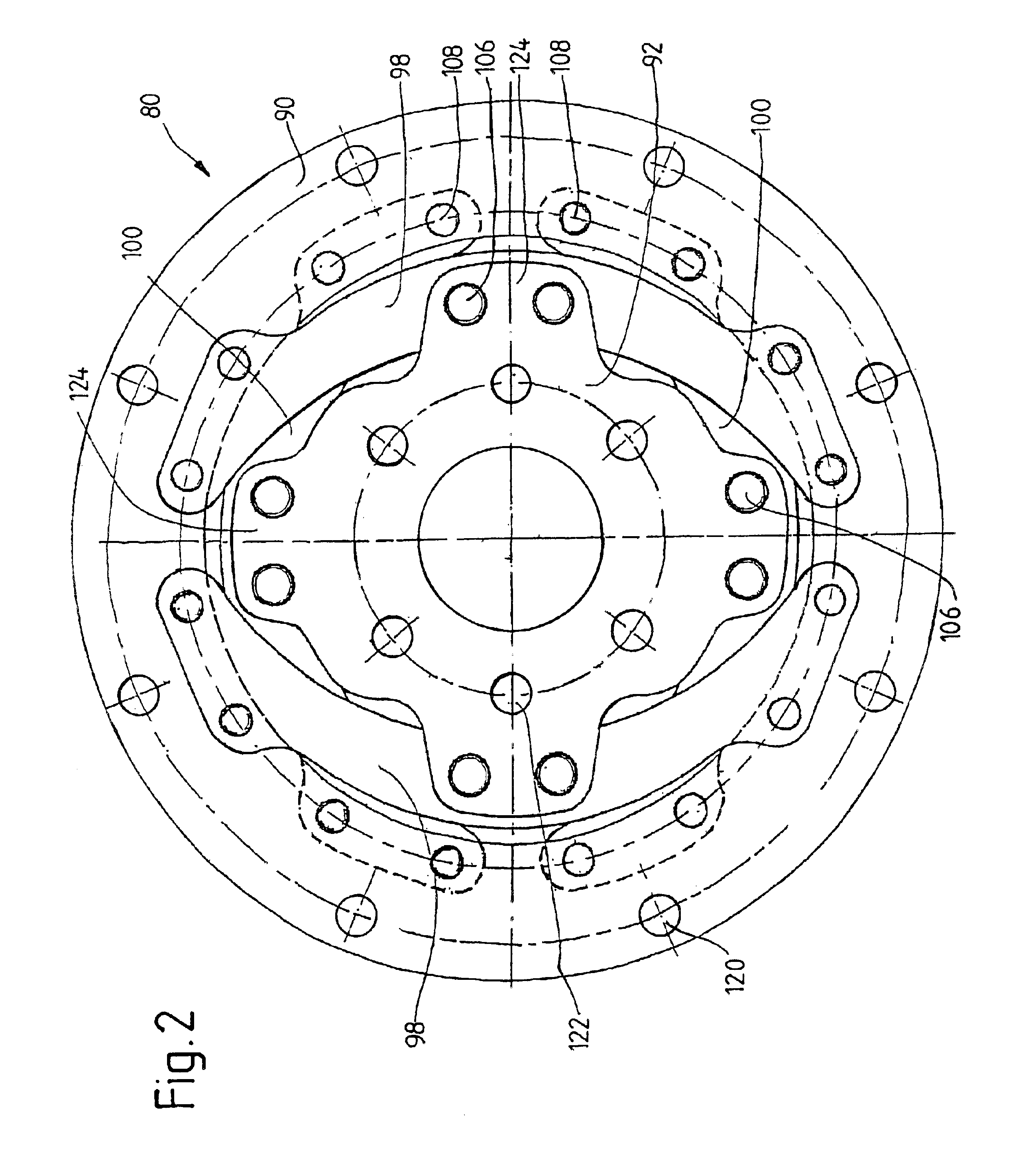
Various aspects of the invention, including advantageous possibilities of further elaboration, are described below on the basis of special exemplary embodiments, namely, so-called dual clutches of the friction disk type, where the exemplary embodiments of FIGS. 1, 4, 5, 8, 10 and 12 show dual clutches of the NORMALLY CLOSED (normally engaged) type, which are actuated (disengaged) by pushing on them. These various inventive aspects, however, are independent of the type of clutch and the method of actuation. The various inventive aspects can be applied both to simple clutches (with only one clutch arrangement) and to dual clutches (or multi-clutch arrangements in general, with two or more clutch arrangements), including clutches of the NORMALLY OPEN and of the NORMALLY CLOSED type, regardless of how they are actuated, that is, regardless of whether clutches are actuated by pushing on them or by pulling on them. At least some of the aspects of the invention and at least one of the poss...


PUM


Abstract

A motor vehicle drive train with a clutch device installed between a drive unit and a transmission having at least one transmission input shaft to transmit torque between the drive unit and the transmission. The clutch device comprises at least one clutch arrangement assigned to a respective transmission input shaft, where an input side of the clutch device is connected directly or indirectly by way of a torque-transmitting arrangement to a connecting end of a power takeoff shaft of the drive unit. The torque-transmitting arrangement has a radially outer connecting area for connection to the clutch device and a radially inner connecting area for the direct or indirect connection to the connecting end by the mediation of at least one positive connecting element, which connects the radially inner connecting area in a positive manner to the connecting end or to a component or assembly attached nonrotatably to the connecting end, and which secures the radially inner connecting area on the connecting end or on the component or assembly in the axial direction. The positive connecting element is located in a central radial area relative to an axis of rotation (A) of the clutch device, which area is essentially the same as or smaller than the radial area occupied by the minimum of one transmission input shaft.

Description

1. Field of the InventionIn accordance with a first particular aspect, the invention pertains to a motor vehicle drive train with a multi-clutch device, especially with a dual clutch device, installed between a drive unit and a transmission to transmit torque between the drive unit and the transmission, where the clutch device comprises a first clutch arrangement assigned to a first transmission input shaft and a second clutch arrangement assigned to a second transmission input shaft, where the transmission input shafts are essentially coaxial to an axis of rotation of the clutch device. A where an input side of the clutch device is connected either directly or indirectly by way of a torque-transmitting arrangement to a connecting end of a power takeoff shaft of the drive unit, and the torque-transmitting arrangement has a radially outer connecting area for the connection to the clutch device and a radially inner connection area for the direct or indirect connection to the connectin...

Claims


Application Information

Patent Timeline
Patent Type & Authority Patents(United States)
IPC IPC(8): F16D13/58F16D13/70F16D21/00F16D13/71F16D21/06
CPCF16D13/70F16D13/71F16D21/06Y02T10/76F16D2021/0607F16D2021/0684F16D2013/706
Inventor ZINK, GEORGORLAMUNDER, ANDREASPAGELS, OLAFVOGT, SEBASTIANHEIARTZ, MARKUS
Owner ZF SACHS AG
Learn More