Door for ticket gate

a technology for ticket gates and doors, applied in the field of new doors for ticket gates, can solve the problems of low expansion ratio of polyurethane foam, heavy door frames, and substantial repair costs, and achieve the effects of facilitating recycling of metal plates and cushioning materials, easy maintenance and convenient recycling

Inactive Publication Date: 2005-01-04
KOKUSHIN SANGYO
View PDF10 Cites 8 Cited by
  • Summary
  • Abstract
  • Description
  • Claims
  • Application Information

AI Technical Summary

Benefits of technology

An object of the present invention is, therefore, to provide a door for a ticket gate, which is lightweight and hence, does not cause much trouble on equipment of the ticket gate and permits easy maintenance of the equipment and further, which permits ready separation of a cushioning material from a metal plate to facilitate their recycling.
According to the present invention, the door is lightweight so that equipment and the like at the ticket gate do not develop much trouble and their maintenance is easy. The cushioning material can be easily removed from the metal plate after replacement, so that recycling of the metal plate and the cushioning material is facilitated. For example, the metal plate so recovered can be used directly as a core material for a new door, while the expanded polyolefin plates as the cushioning material can be used as a resin material for a variety of molded or otherwise formed products.

Problems solved by technology

As polyurethane resin is high in specific gravity and the cushioning material is required to have a certain degree of strength, the polyurethane foam has a low expansion ratio and as a consequence, the door becomes heavy.
Since the door arranged at the ticket gate with such complex structures built therein as described above is heavy, the equipment in the ticket gate are often caused to develop troubles due to impacts exerted upon opening and closure of the door, resulting in a substantial cost for their repair.
In practice, however, its is extremely difficult to separate the iron plate and the polyurethane foam from each other because they are integrated together as described above.

Method used


Image

  • Door for ticket gate
  • Door for ticket gate
  • Door for ticket gate

Examples


first embodiment

In the first embodiment illustrated in FIG. 4, the expanded polyolefin plates 7,7 are substantially not fusion-bonded to the corresponding surfaces of the iron plate 1 and are substantially not fusion-bonded together in the through-holes 2, when the press molding temperature is relatively low. When the expanded polyolefin plates 7,7 are substantially not fusion-bonded together in the through-holes 2 of the iron plate 1 as mentioned above, the door, depending upon its application field, may develop a problem during use such that the expanded polyolefin plates 7,7 may blister or otherwise bulge outwards or may undergo sagging.

The second embodiment shown in FIGS. 5 and 6 has overcome the above-mentioned problem which may occur when the press molding temperature is relatively low. The second embodiment is different from the first embodiment illustrated in FIGS. 3 and 4 in that as depicted in FIG. 5, a uniting sheet or film 12 is held between the iron plate 1 and the lower expanded polyo...

third embodiment

The third embodiment shown in FIG. 8 includes a skin 11 arranged on surfaces of expanded polyolefin plates 7,7. This skin 11 can be formed by arranging sheets or films, which serve to make up the skin 11, between the expanded polyolefin plates 7,7 and the top and bottom forces 8, 9, respectively, in the step depicted in FIG. 5 and then conducting press molding as illustrated in FIG. 6. The skin 11 is fusion-bonded to the entire outer surfaces of the expanded polyolefin plates 7,7 by heat applied upon heated pressing. As the sheets or films which are used to make up the skin 11, thermoplastic resin sheets excellent in heat resistance and strength or sheets of a woven, knitted or nonwoven fabric impregnated with a thermoplastic resin can be used. For example, sheets of a woven nylon fabric impregnated with an ethylene-vinyl acetate copolymer and commercially available under the trade name of “Eveterpolin” from K. K. Futaba Shokai can be used suitably. These sheets or films may be colo...

fourth embodiment

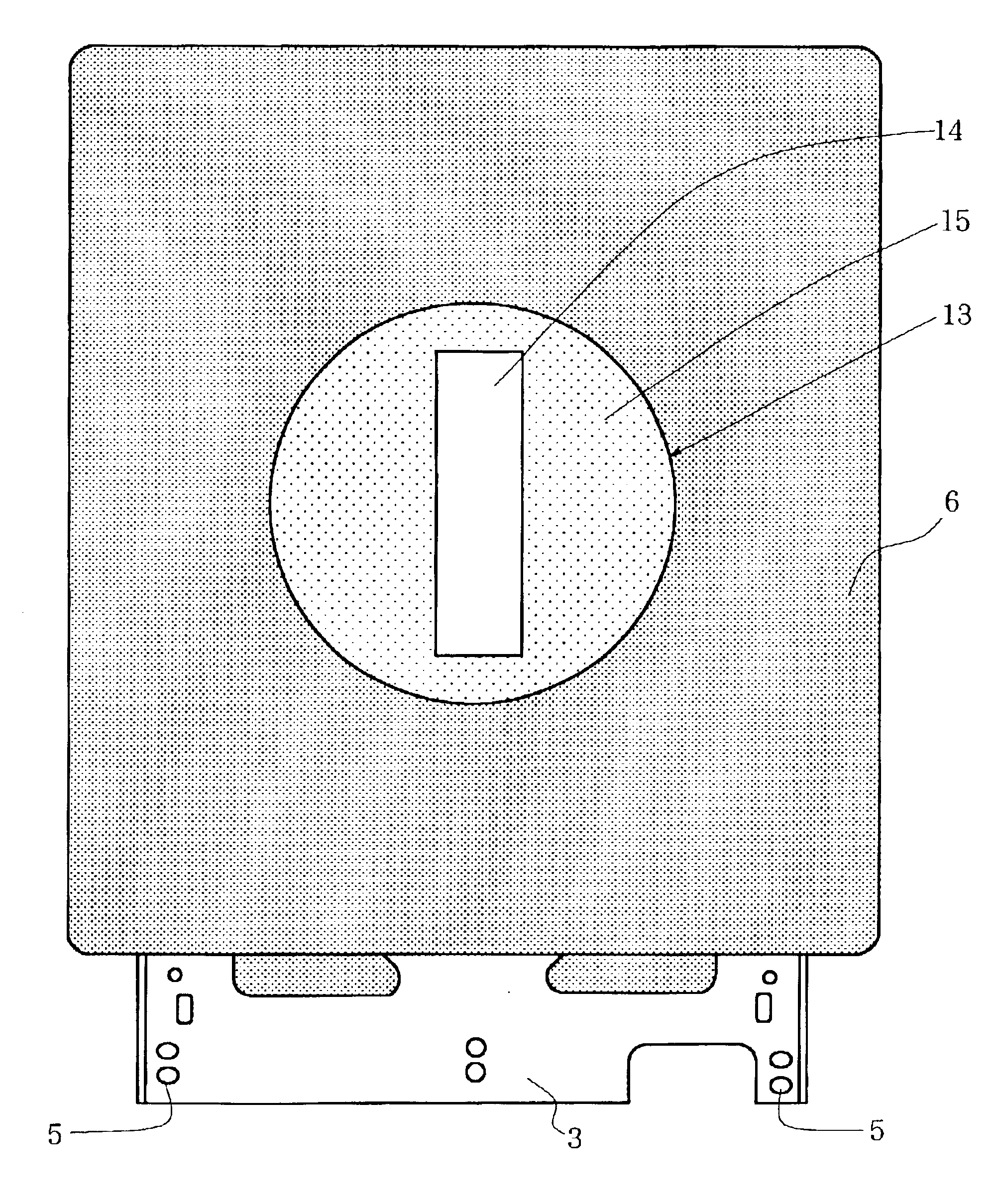
The above-described problem of the conventional technique can also be fully overcome by the present invention as illustrated in FIGS. 9A to 9D and FIG. 10. FIG. 9A illustrates an expanded polyolefin plate 7 for use in the present invention, which is provided at a central part thereof with a circular hole 16. Needless to say, the circular hole 16 can be formed at a desired location other than the central part. In general, the formation of the hole 16 can be easily conducted by punching. A disc-shaped block 17 depicted in FIG. 9B has been cut out by punching, for example, from an expanded polyolefin plate colored in red (not shown) This expanded polyolefin plate may preferably be made of the same material as the expanded polyolefin plate shown in FIG. 9A except for a difference in color. The disc-shaped block 17 is centrally provided with a rectangular opening 18, and has an outer diameter substantially equal to an inner diameter of the circular hole 16 depicted in FIG. 9A. A substant...


PUM

PropertyMeasurementUnit
temperaturesaaaaaaaaaa
thicknessaaaaaaaaaa
diameteraaaaaaaaaa

Abstract

A door for a ticket gate is disclosed. The door is composed of a metal plate as a core material and a cushioning material covering the metal plate. The metal plate defines at least one through-hole therein. The cushioning material comprises expanded polyolefin plates, and the metal plate and the expanded polyolefin plates have been integrated together by arranging the polyolefin plates on opposite sides of the metal plate, respectively, and then press molding them together.

Description

FIELD OF THE INVENTIONThis invention relates to a novel door for a ticket gate composed of a metal plate, for example, an iron plate as a core material and a cushioning material covering the metal plate. More specifically, this invention is concerned with a door for a ticket gate, which is lightweight and hence, does not cause much trouble on equipment of the ticket gate and permits easy maintenance of the equipment and further, which permits ready separation of a cushioning material from a metal plate to facilitate their recycling.DESCRIPTION OF THE BACKGROUNDA number of automatic ticket gates are arranged at a railway station. Insertion of a ticket, pass or prepaid card into such an automatic ticket gate opens a door arranged at an end of the ticket gate or doors disposed at opposite ends of the ticket gate (only one door will hereinafter be referred to for the sake of brevity in description) so that boarding of a train without a valid ticket, pass or prepaid card can be prevented...

Claims


Application Information

Patent Timeline
Patent Type & Authority Patents(United States)
IPC IPC(8): B29C43/36B29C43/18B29C43/38B29C65/02B32B15/08B32B27/32B29C70/00B29C70/88B29C70/70B32B5/18E06B11/00E06B11/08E06B11/02E06B3/70E06B3/82E06B3/86
CPCB29C43/18B29C66/727B29C65/02B29C66/433B29C70/70B29C70/885B32B5/18B32B15/08B32B27/32E06B11/02E06B11/085B29C43/38B29C65/00B29K2105/04B29K2105/256B29K2705/00E06B3/7001E06B3/86B29C66/1122B29C66/71B29C66/83221B29K2023/06B29K2023/10B29K2023/12B29K2023/00
Inventor SUDO, KUNIO
Owner KOKUSHIN SANGYO
Why Eureka
Try Eureka